Compound ejector

An ejector and duplex technology, applied in jet pumps, non-displacement pumps, machines/engines, etc., can solve the problem of reducing injection ratio and mixing efficiency, lowering injection coefficient or injection ratio, contact rate and Low entrainment efficiency and other problems, to achieve the effect of reduced axial size and weight, various structural forms, and wide application range

Inactive Publication Date: 2014-07-23
韩铁夫
View PDF7 Cites 0 Cited by
  • Summary
  • Abstract
  • Description
  • Claims
  • Application Information

AI Technical Summary

Problems solved by technology

However, the primary fluid jet is located in the center of the mixing chamber, and the secondary fluid is entrained around the primary fluid jet beam. The larger the diameter of the primary fluid jet, the lower the contact rate and entrainment efficiency between the primary fluid and the secondary fluid per unit volume, that is The injection coefficient or injection ratio becomes lower, which greatly reduces the suction function of the injection pump. In order to improve the efficiency of the injection pump, the existing solution is to divide the main fluid jet into several strands, that is, to use multi-nozzle jets, but These did not change the initial distribution state of the primary fluid in the center and the secondary fluid in the periphery
Because of the occlusion of the surrounding streams, it is still difficult for the secondary fluid to be pumped into the central area of ​​the main fluid jet for mixing, which will inevitably reduce the injection ratio and mixing efficiency.
In order to make the main fluid and the secondary fluid sucked in by the outer periphery can be mixed with each other and fully heat transfer, mass transfer, and pressure equalization mixing, for the single-tube priming that mainly relies on the turbulent diffusion of the jet in the long stroke of the mixing tube for mixing If the ejector is used, it is necessary to increase the length of the mixing tube (or mixing diffuser), which results in low injection efficiency and excessive axial dimension of the injection pump.

Method used


Image

  • Compound ejector
  • Compound ejector
  • Compound ejector

Examples


Embodiment 1

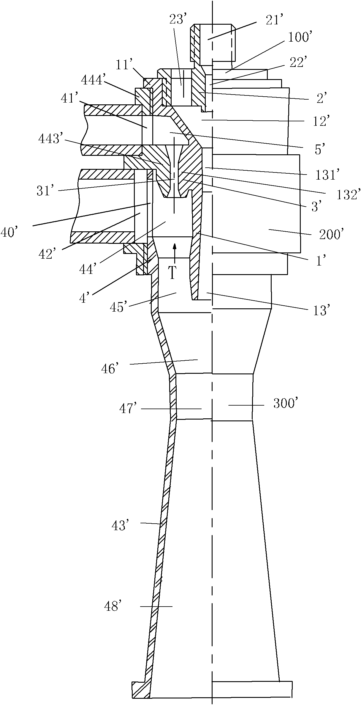
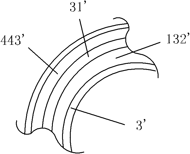
[0048] For the structure of Embodiment 1 of the compound ejector of the present invention, see figure 1 . The compound ejector includes a central ejector 100', an annular ejector 200', and a total ejector 300'. The central nozzle 22' on the inner pipe 1' and the central nozzle seat 2' forms a central ejector 100', and the outer side of the first half of the inner pipe 1' and the inner side of the first half 444' of the outer pipe 4' form an annular nozzle seat 3' and an annular The nozzles 31' and form the annular ejector 200'. The central ejector 100' is coaxially arranged in the annular ejector 200', and the nozzle of the central ejector 100' is connected with the outlet of the surrounding annular ejector 200' and the inner assembly of the rear part 43' in the outer tube 4'. The mixing chamber 46', the overall mixing tube 47' and the overall diffuser tube 48' together constitute the overall ejector 300'.

[0049] Central nozzle seat 2' is provided with central nozzle 22' ...

Embodiment 2

[0059] For the structure of the second embodiment of the compound ejector of the present invention, see Figure 4 . This embodiment includes a central ejector 100 , a circular ejector 200 , a general ejector 300 and a central pre-stage ejector. The middle section of the central ejector 100 is coaxially fixed to the inlet of the diameter-expanding section at the front end of the annular ejector 200, and the rear section of the central ejector 100 is coaxially sleeved in the annular ejector 200 and suspended inside. Around the nozzle of the central mixing tube 13 output end of the central ejector 100, the outlet of the annular mixing tube 45 output end of the annular ejector 200 ejected by it is established, and they are directly connected to the total mixing chamber 46 and the total mixing output pipe 47 to form a total. Ejector 300 .

[0060] The main body of the central ejector 100 is a central nozzle seat 2 arranged in sequence along the central axis front and back and a s...

Embodiment 3

[0069] Such as Figure 8 , Figure 9 , Figure 10 shown. The basic structure and working mechanism of this embodiment are basically the same as those of the first embodiment. The same part will not be described again, the difference is:

[0070] A. Central injector part: the structure of the lower part of the inner tube 10' is basically the same as that of the inner tube 10 in the first embodiment, the difference lies in that the top of the large-diameter flared opening on the upper part of the inner tube 10' shrinks upward and extends out The central short pipe 110' can be or is provided with a first main fluid inlet pipe 210' and directly leads to the central nozzle seat 20' and the central nozzle 220'. The large-diameter trumpet-shaped expansion port on the top of the inner tube 10' shrinks downwards into a small-diameter central mixing tube 130'. The inner cavity of the large-diameter trumpet-shaped expansion port on the top of the inner pipe 10' is the central mixing...


PUM


Abstract

The invention provides a compound ejector and relates to a fluid mixing element for fluids. A central ejector of the compound ejector is coaxially arranged in an annular ejector; outlets of the central ejector and the annular ejector are communicated with a main mixing chamber and a main mixing tube; a first main fluid is ejected from the top of the central ejector to an inlet of a central mixing tube through a central nozzle, is utilized to inject a secondary fluid entering into a central mixing chamber from a surrounding inlet at the top of the central ejector into a central mixing tube and is mixed with the secondary fluid; a second main fluid is ejected from a side position at the top of the annular ejector to an inlet of an annular mixing tube through an annular nozzle, is utilized to inject the secondary fluid entering into an annular mixing chamber from an inlet on the side position on the upper part of the annular ejector into the annular mixing tube and is mixed with the secondary fluid; and an ejected fluid at the outlet of the central mixing tube in the main mixing chamber is utilized to inject the ejected fluid at the outlet of the annular mixing tube into the main mixing tube and is mixed for the third time, thereby finishing the mixed fluid conveying in a way that the high-pressure main fluid pumps the low-pressure secondary fluid. The compound ejector is short in axial size and high in pumping and ejecting efficiency.

Description

technical field [0001] The invention relates to a flow mixing element for fluids with different pressures, in particular to a compound injector. Background technique [0002] Ejector is also called jet pump, it is a mixed flow element that uses high pressure primary fluid to eject low pressure or no pressure secondary fluid, and outputs medium pressure mixed fluid. The most typical structure among the existing ejectors is the Venturi ejector. The body of the Venturi ejector of this single-tube ejector is a long circular tube with a diameter-expanding section at the front end, and a nozzle is installed at the front end of the body , a secondary fluid inlet is set on the side of the body. The inlet of the nozzle communicates with the inlet of the main fluid, and the outlet of the nozzle extends into the diameter-expanding section of the body, so that the diameter-expanding section of the body becomes the mixing chamber of the Venturi ejector. On the body, the small-diameter ...

Claims


Application Information

Patent Timeline
Patent Type & Authority Patents(China)
IPC IPC(8): F04F5/00
Inventor 韩铁夫
Owner 韩铁夫
Why Eureka
Try Eureka