A jet mixer

A technology for ejectors and flow mixers, which is applied in the direction of fluid mixers, mixers, jet pumps, etc., and can solve the problem that high-efficiency injection mixers are not suitable, the axial size and weight of the ejector are large, and the installation and use are unfavorable etc. to solve the problems of low ejection efficiency, reduced length, weight and size, and shortened length

Inactive Publication Date: 2016-01-20
韩铁夫
View PDF7 Cites 0 Cited by
  • Summary
  • Abstract
  • Description
  • Claims
  • Application Information

AI Technical Summary

Problems solved by technology

[0006] The existing injection mixer mainly relies on the turbulent diffusion of the jet in the long stroke of the mixing tube to mix the main fluid and the secondary fluid. The turbulent diffusion of the jet needs a development and strengthening in the mixing tube. Therefore, the ejector must have a slender mixing tube (or mixing diffuser tube), and the large-flow ejector needs a large-diameter mixing tube. The larger the caliber, the more the length of the mixing tube needs to be greatly increased, resulting in Disadvantages of excessive axial size and weight of larger ejectors
This is very unfavorable for installation and use in many occasions that require small volume and light load
Although a large jet pump can be formed by connecting multiple small jets in parallel, its function is mainly for pumping, and its structure is relatively special, so it is not suitable for high-efficiency jet mixers that require small size and light weight.

Method used


Image

  • A jet mixer
  • A jet mixer
  • A jet mixer

Examples


Embodiment 1

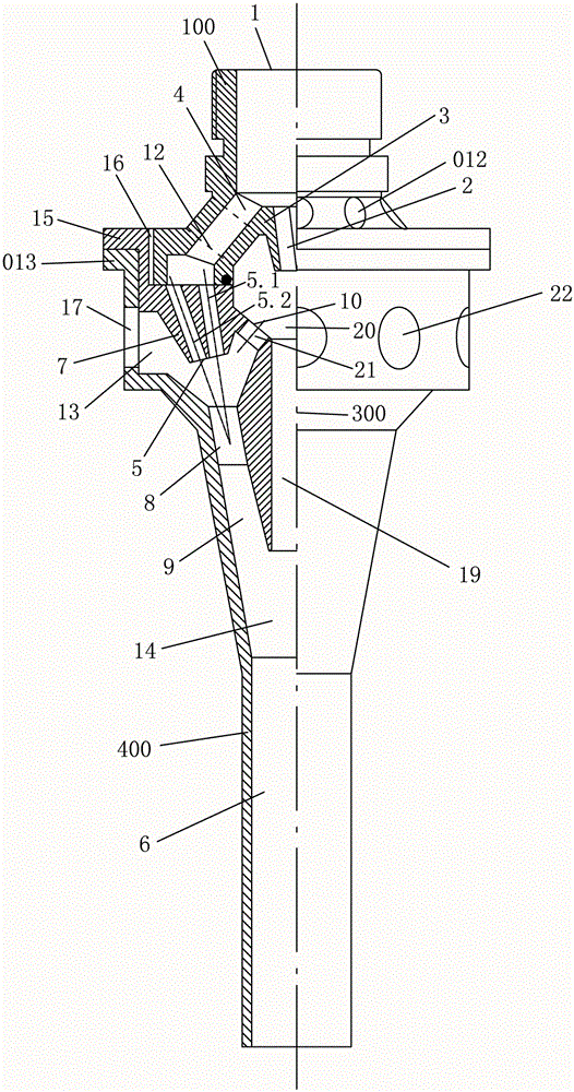
[0042] Example 1 see figure 1 ,

[0043] The injection mixer in this embodiment uses a main fluid to inject the secondary fluid from the porous upper port 012 of the secondary fluid and the porous side port 22 of the secondary fluid, and outputs the mixed fluid from the total mixing output pipe 6. device. The secondary fluid inlet / pipe and the main fluid inlet pipe are respectively arranged on the side of the inlet section of the ejector mixer and at both ends of the axis of the ejector mixer, which are respectively connected to the central ejector and the outer ring ejector; the central ejector The front part of the outer ring ejector and the outer ring ejector are concentrically fixed, and the middle and rear parts of the two are concentrically nested; the output port of the outer ring ejector is surrounded by the output nozzle of the central ejector, and they are directly connected to the main mixing chamber and the main ejector of the main ejector. Its total mixing pipe;...

Embodiment 2

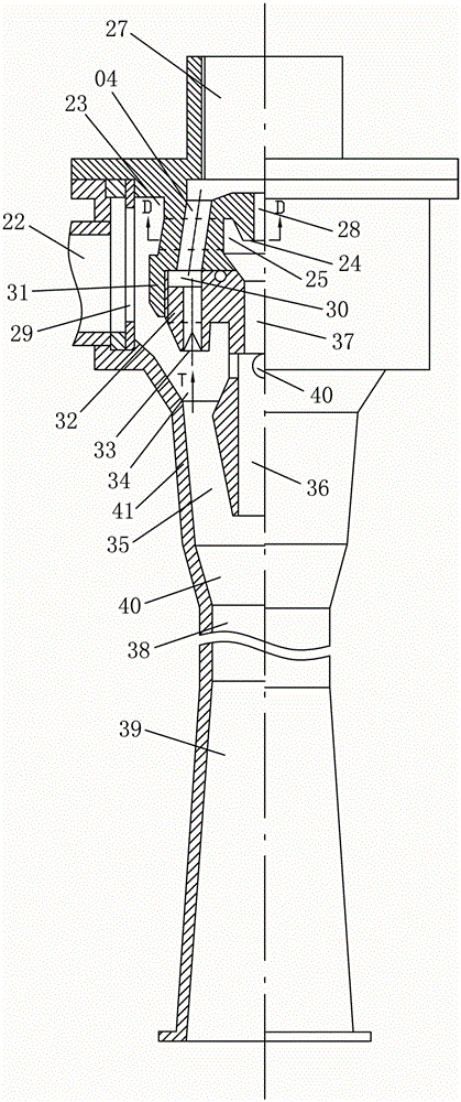
[0050] Embodiment 2 see Figure 2-6

[0051] The jet mixer in this embodiment uses a primary fluid to inject a secondary fluid and outputs a mixed fluid. There is a central ejector and an outer ring ejector, the former is coaxially set in the latter, and both have the same main fluid inlet pipe and common total mixing output pipe. Its structure is roughly the same as the previous example. The same parts will not be described again, and the differences are as follows:

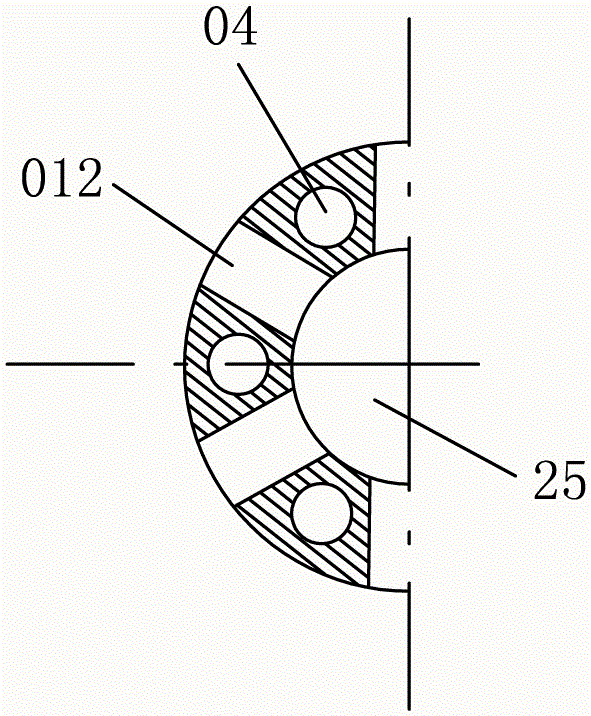
[0052] In this embodiment, the inner tube is in the shape of a flat umbrella, with a funnel-shaped central hole inside, and extends downwards into a central throat 37 and a central mixing tube 36 thereof; image 3 As shown, the central outlet hole of the main fluid inlet pipe 27 is provided with a central nozzle 24, and the lower part of the main fluid inlet pipe 27 is expanded into an annular flow distribution sleeve 31, and vertical porous main fluid passages are evenly distributed on the peripheral wall of...

Embodiment 3

[0059] Embodiment 3 see Figure 7 , 8 ,9

[0060] The injection mixer of this embodiment is also a kind of injection mixer that uses a main fluid to inject a secondary fluid and outputs a mixed fluid. It is coaxially set by the central injector and the outer ring injector. The two have a central main fluid inlet pipe and a common total mixing outlet pipe 53, and a common secondary fluid inlet pipe 42 is arranged horizontally on the side of the annular mixing chamber. This embodiment is basically the same as Embodiment 2, and the common place is no longer expressed, and the difference lies in:

[0061] In this implementation, only one secondary fluid inlet pipe is provided in the jet mixer, and the annular mixing chamber 43 is not provided with a uniform annular distribution sleeve. In order to improve the uniform supply of the secondary fluid and facilitate the injection mixing, the axis of the secondary fluid inlet pipe horizontally positioned on the side of the annular mi...


PUM


Abstract

An injection flow mixer which includes a central ejector, an outer ring ejector, and a total ejector; the central ejector is coaxially arranged in the outer ring ejector, and the front parts of the two are concentrically fixed, and the middle of the two The rear part is concentrically nested; the output port of the outer ring ejector is surrounded by the output nozzle of the central ejector, and they are directly connected to the total mixing chamber of the total ejector and its total mixing tube. Compared with the prior art, the invention has the advantages of small weight and axial dimension, high ejection rate and good performance at high flow rate.

Description

technical field [0001] The invention relates to a mixed flow injection device, in particular to a jet mixer for mixed fluid injection. Background technique [0002] The injection mixer is a device that injects a low-pressure (or no-pressure) secondary fluid with a relatively high-pressure primary fluid, and completes the suction of the secondary fluid by the primary fluid for mixed-flow injection or delivery. Since the injection mixer has no moving parts, it is reliable in use and widely used in fluid equipment in various fields. [0003] Existing typical jet mixers consist of a primary fluid inlet pipe, a nozzle, a secondary fluid inlet, a mixing chamber, a throat or a mixing diffuser. The secondary fluid passed into the mixing chamber is sucked into the mixing tube by the jet of the primary fluid nozzle, and the primary and secondary fluid is output from the mixing diffuser tube after being mixed and equalized. This ejector generally has a central nozzle and a single elo...

Claims


Application Information

Patent Timeline
Patent Type & Authority Patents(China)
IPC IPC(8): F04F5/00
CPCF04F5/463B01F25/31232B01F25/31243
Inventor 韩铁夫
Owner 韩铁夫
Why Eureka
Try Eureka