Multiplex compound ejector

A technology of ejector and mixing tube, which is applied in the field of multi-channel compound ejector, can solve the problem of low efficiency of a single ejector, and achieve the effects of wide working range, compact overall structure, and short length of mixing tube

Inactive Publication Date: 2015-09-02
韩铁夫 +1
View PDF8 Cites 0 Cited by
  • Summary
  • Abstract
  • Description
  • Claims
  • Application Information

AI Technical Summary

Problems solved by technology

[0007] The purpose of the present invention is to overcome the shortcomings of the existing ejector structure with a single ejection efficiency and provide a multi-channel compound ejector with compact size, high ejection rate and good performance at high flow rate

Method used


Image

  • Multiplex compound ejector
  • Multiplex compound ejector
  • Multiplex compound ejector

Examples


Embodiment 1

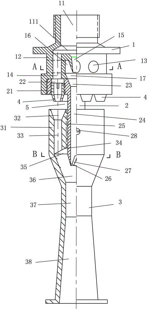
[0036] One embodiment of the multi-channel composite injector of the present invention adopts a high-pressure primary fluid input from the front end, a low-pressure or no-pressure secondary fluid input from the side, and a pressurized mixed flow output from the tail. Its structure, such as figure 1 As shown, it includes a main fluid assembly 1 , an inner pipe assembly 2 , an outer pipe collar 3 and six peripheral nozzles 4 .

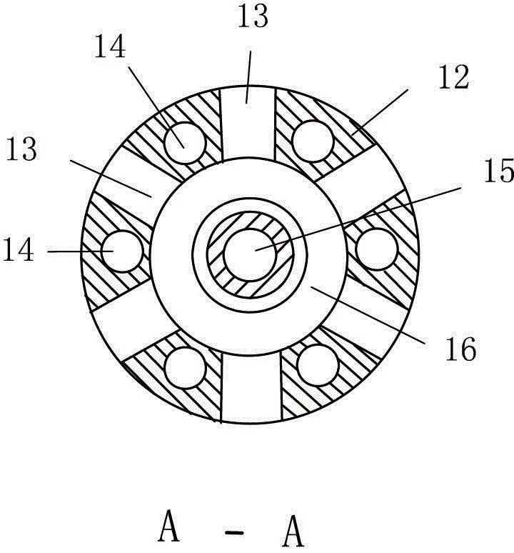
[0037] The center of the top (front end) of the main fluid assembly 1 is provided with a main fluid inlet pipe 11 upwards and a central nozzle 15 downwards. The lower part of the main fluid assembly 1 is provided with an annular distribution sleeve 12, see figure 2 A plurality of horizontal secondary fluid holes 13 and a plurality of vertical primary fluid holes 14 are provided on the peripheral wall of the annular distribution sleeve 12 , and the secondary fluid holes 13 and the primary fluid holes 14 are cross-isolated. The inner cavity of the annula...

Embodiment 3

[0060] In this embodiment, a high-pressure main fluid is input from the front end, a low-pressure or no-pressure secondary fluid is injected from the side, and a mixed flow is output from the tail. Its structure is as follows Figure 5 As shown, it includes the main fluid assembly 100, the inner pipe assembly 200, an outer pipe collar 300 and its extension extension pipe 300' and a central nozzle assembly 1500.

[0061]The top (front end) of the main fluid assembly 100 is centrally provided with a main fluid inlet pipe 1100, and its lower end is provided with an annular flange; The peripheral flanges provided are sealed butt-connected, and a diameter-expanding cavity 11100 is formed in the flared jacket 21100 at the top of the annular flow distribution sleeve 2100 . Six lateral secondary fluid holes 21300 and six vertical primary fluid holes 21400 are provided on the peripheral wall of the annular distribution sleeve 2100 , and the secondary fluid holes 21300 are cross-is...


PUM


Abstract

A combined jet with multiple pipes comprises a fore composite annular jet, a central jet and a post main jet. The central jet is co-axially arranged within the composite annular jet, and they share a primary fluid input pipe together. The main jet is deposited behind both combined annular jet and central jet, and is also co-axially connected in series with them. The combined jet with multiple pipes has high efficiency, and the volume to be guided is relatively large.

Description

technical field [0001] The invention relates to a mixed-flow injection device, in particular to a multi-channel compound ejector for mixed fluid injection. Background technique [0002] The ejector is a device that injects a low-pressure (or no-pressure) secondary fluid with a relatively high-pressure primary fluid, and completes the suction of the secondary fluid by the primary fluid for mixed-flow injection or delivery. Since the ejector has no moving parts, it is reliable and widely used in fluid equipment in various fields. [0003] Existing typical ejectors are composed of primary fluid inlet pipe, nozzle, secondary fluid inlet, mixing chamber, throat or mixing diffuser. The secondary fluid passed into the mixing chamber is sucked into the mixing tube by the jet of the primary fluid nozzle, and the primary and secondary fluid is output from the mixing diffuser tube after being mixed and equalized. This ejector generally has a central nozzle and a single elongated mixi...

Claims


Application Information

Patent Timeline
Patent Type & Authority Patents(China)
IPC IPC(8): F04F5/10F04F5/44
CPCF04F5/467
Inventor 韩铁夫韩笃坤
Owner 韩铁夫
Why Eureka
Try Eureka