
Calibration method and angle measuring method for an angle measuring device, and angle measuring device

A technology of angle measurement and calibration method, which is applied in the direction of measuring devices, using electric/magnetic devices to transfer sensing components, instruments, etc., which can solve the problems of no recalibration, complicated calibration, and difficult external positioning of sensors with high precision

Active Publication Date: 2015-05-06
LEICA GEOSYSTEMS AG
View PDF7 Cites 0 Cited by
  • Summary
  • Abstract
  • Description
  • Claims
  • Application Information

AI Technical Summary

Problems solved by technology

This makes calibration extremely complicated, especially after the goniometer is fitted to the device
[0017] Furthermore, there is no easy solution for recalibrating finished devices in order to be able to react, for example, to changing environmental conditions or potential sources of error such as shock effects and knocking effects, since the high-precision exterior of the sensors installed in the device Locating is often difficult or even possible

Method used


Image

  • Calibration method and angle measuring method for an angle measuring device, and angle measuring device
  • Calibration method and angle measuring method for an angle measuring device, and angle measuring device
  • Calibration method and angle measuring method for an angle measuring device, and angle measuring device

Examples


Embodiment Construction

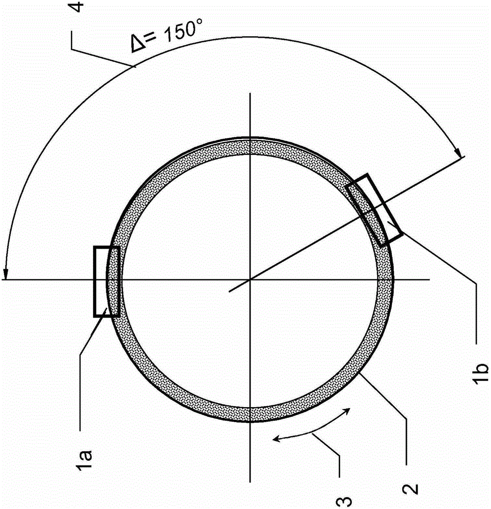
[0095] exist Figure 1a A possible embodiment of the angle measuring system according to the invention can be seen in a schematic diagram.

[0096] An angle measuring system 7 has:

[0097] ■Coding carrier 2 with absolute position coding,

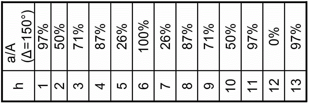
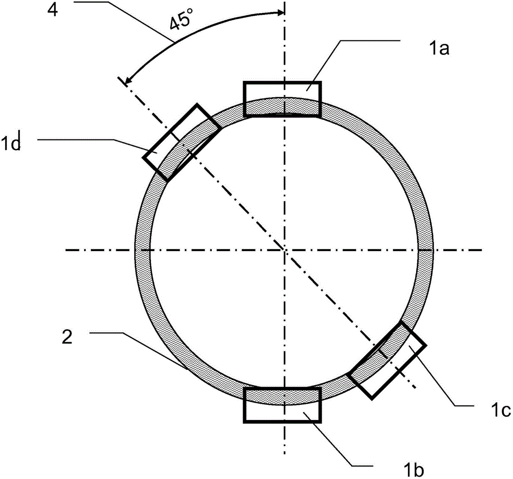
[0098] ■ at least two read heads 1a, 1b, which have a fixed, known angular position 4, which have an angular distance relative to each other, in particular greater than 50 degrees, for example 70 degrees to 180 degrees, preferably 140 degrees degrees to 170 degrees, for example 150 degrees, and the read heads are respectively adapted to at least partially detect the position code, so that the absolute angular position value of the corresponding read head 1a, 1b relative to the code carrier 2 can be determined, and wherein the code carrier 2 can be rotated relative to the read head 1a, 1b and thus can occupy different angular positions 3 of the code carrier 2 relative to the read head 1a, 1b, and

[0099] ■ An analysis unit (not shown) for...


PUM


Abstract

The invention relates to a calibration method that can be carried out without a reference system for an angle measuring device having a code carrier carrying an absolute position code, and at least two reading heads comprising a fixed, known angle position at an angular distance, wherein the code carrier can be rotated relative to the reading heads, and different angle positions of the code carrier relative to the reading heads can thus be captured. Angle position values of the reading heads in an angular setting are determined and angular error is determined, which are repeated. And, a mathematical analysis method is performed, including determining the parameters of a mathematical function quantifying the angular error, and determining calibration parameters as parameters of the quantifying mathematical function or as a correction or code table derived from the parameters.

Description

technical field [0001] The invention relates to a calibration method for an angle-measuring device and an angle-measuring method, as well as a computer program product for carrying out the method and an angle-measuring device, with which systematic measuring errors can be compensated. Background technique [0002] Angle measuring systems have been known in various embodiments for many years. Angle measuring systems are used, for example, in various measuring devices, such as geodetic measuring devices, coordinate measuring devices or robots, but also in machine and plant construction. In its application, the task is to determine an angular deviation between two subsystems rotatable relative to one another in one degree of freedom or a correspondingly derived variable such as velocity or acceleration. [0003] For example, such angle measuring systems are used in coordinate measuring devices, for example in joint rods, for determining the angular position in the respective j...

Claims


Application Information

Patent Timeline
IPC IPC(8): G01D5/244
CPCG01D18/001G01D5/2449
Inventor 海因茨·利普纳U·沃金格克努特·西尔克斯
Owner LEICA GEOSYSTEMS AG
Learn More