
A typesetting system for multi-plate side-by-side lithography

A technology of lithography and array light sources, applied in the field of multi-plate side-by-side lithography typesetting systems, can solve the problems of huge individualized production costs, achieve stable angle positions, ensure lithography quality, and improve production efficiency

Active Publication Date: 2020-08-11
UNIV OF SHANGHAI FOR SCI & TECH
View PDF4 Cites 0 Cited by
  • Summary
  • Abstract
  • Description
  • Claims
  • Application Information

AI Technical Summary

Problems solved by technology

[0003] Traditional lithography technology can only cope with mass production, and the cost of personalized production is huge

Method used


Image

  • A typesetting system for multi-plate side-by-side lithography
  • A typesetting system for multi-plate side-by-side lithography
  • A typesetting system for multi-plate side-by-side lithography

Examples


Embodiment Construction

[0035] The following will clearly and completely describe the technical solutions in the embodiments of the present invention with reference to the accompanying drawings in the embodiments of the present invention. Obviously, the described embodiments are only some, not all, embodiments of the present invention. Based on the embodiments of the present invention, all other embodiments obtained by persons of ordinary skill in the art without making creative efforts belong to the protection scope of the present invention.

[0036] In describing the present invention, it should be understood that the terms "longitudinal", "transverse", "upper", "lower", "front", "rear", "left", "right", "vertical", The orientation or positional relationship indicated by "horizontal", "top", "bottom", "inner", "outer", etc. are based on the orientation or positional relationship shown in the drawings, and are only for the convenience of describing the present invention and simplifying the descriptio...


PUM


Abstract

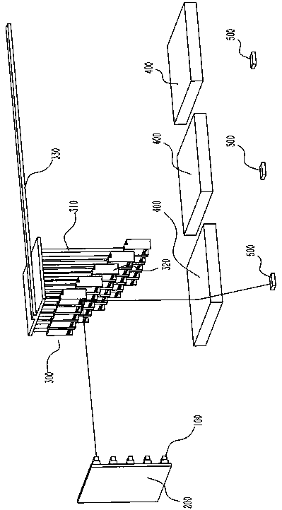
The invention discloses a typesetting system for multi-plate parallel photolithography, which comprises an array light source arranged on a vertical plate; Typesetting device, the typesetting device comprises a shelf, a reflective unit one-to-one corresponding to the array of light sources mounted on an associated gantry, The reflecting unit is provided with a reflecting mirror and an opening / closing device, and the gantry is connected with a slide rail, and the slide rail is provided with a driving mechanism for sliding the gantry, and the reflecting unit is staggered and discharged on a vertical height so that each reflecting unit can receive irradiation corresponding to the array light source; A plurality of optical image reduction devices arranged below the moving direction of the slide rail; A plurality of boards to be printed; And the controller. The invention has the beneficial effect of improving production efficiency, and has little influence on typesetting change, and is sufficient to satisfy personalized production.

Description

technical field [0001] The invention belongs to the field of photolithography, and in particular relates to a typesetting system for multi-plate parallel photolithography. Background technique [0002] Photolithography technology refers to the technology of transferring the pattern on the mask plate to the substrate by means of photoresist (also known as photoresist) under the action of light. The main process is as follows: first, ultraviolet light is irradiated on the surface of the substrate with a layer of photoresist film through the mask plate, causing the photoresist in the exposed area to undergo a chemical reaction; Photoresist (the former is called positive photoresist, the latter is called negative photoresist), so that the pattern on the mask plate is copied to the photoresist film; finally, the pattern is transferred to the substrate by etching technology. [0003] Traditional lithography technology can only cope with mass production, and the cost of personaliz...

Claims


Application Information

Patent Timeline
Patent Type & Authority Patents(China)
IPC IPC(8): G03F7/20
CPCG03F7/70141G03F7/70175G03F7/70733
Inventor 陈莹常敏孟庆涛邢国军
Owner UNIV OF SHANGHAI FOR SCI & TECH
Learn More