Wind resisting device for roller shutter door

A technology of rolling doors and reels, which is applied in the field of doors and windows, can solve the problems of bending deformation of rolling doors, damage of rolling doors, local gaps, etc., and achieve the effect of moving balance, good wind resistance performance and stable wind resistance components

Inactive Publication Date: 2012-09-26
HUNAN SHINILION ENERGY SAVING SCI & TECH
View PDF7 Cites 7 Cited by
  • Summary
  • Abstract
  • Description
  • Claims
  • Application Information

AI Technical Summary

Problems solved by technology

[0002] The rolling door is mainly fixed by the surrounding frame. Since the rolling door is usually made of some metal strips connected to each other, due to the limitations of the structure and material properties of the rolling door itself, the wind resistance of the rolling door is relatively weak, especially in the industry. Due to the large height and widt

Method used


Image

  • Wind resisting device for roller shutter door
  • Wind resisting device for roller shutter door
  • Wind resisting device for roller shutter door

Examples


Embodiment 1

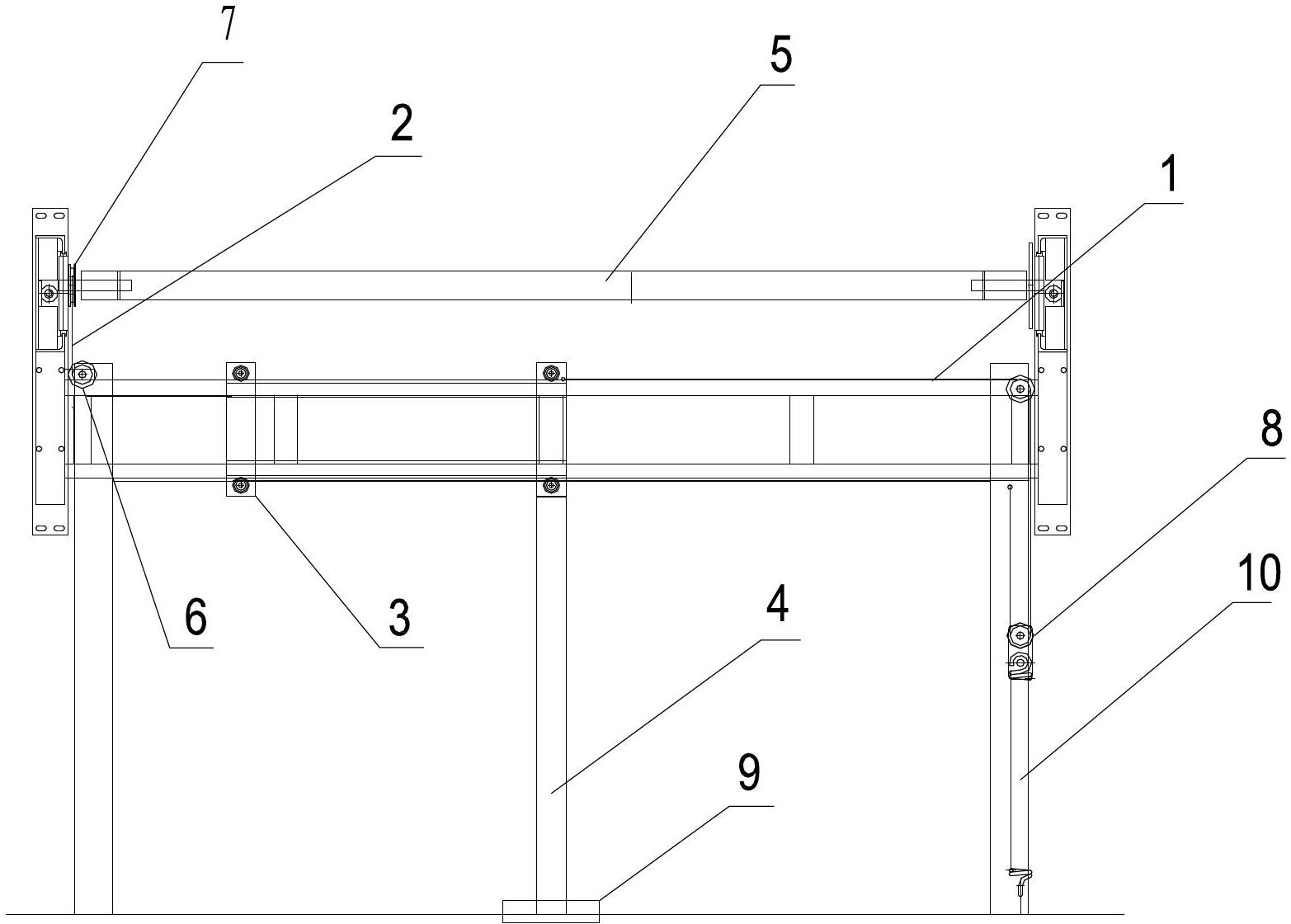
[0030] Such as figure 1 As shown, a wind-resistant device for a rolling door includes a bracket 1, a traction assembly 2, a walking assembly 3 and a wind-resistant assembly 4;

[0031] The support 1 is installed horizontally on the side of the rolling shutter door close to the inside of the door, under the reel 5, and the first end of the support 1 is equipped with a fixed pulley 6;

[0032] The traction assembly 2 is generally a flexible assembly such as a rope or a chain. One end of the traction assembly 2 is wound and fixed on the reel 5, and the other end of the traction assembly 2 is fixed on the walking assembly 3. The traction assembly 2 Across the fixed pulley 6, the preferred winding and fixing method is to fixedly install a reel 7 on one end of the reel 5, and a corresponding guide groove is provided on the reel 7, and the traction assembly 2 is wound on the On the reel 7, when the shutter door is opened or closed, the reel 5 rotates, and the traction assembly 2 is ...

Embodiment 2

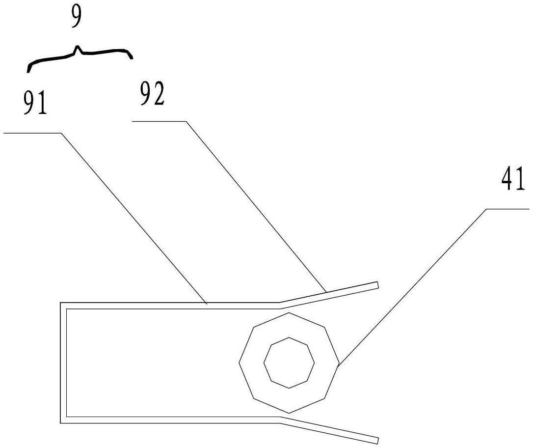
[0037] combine figure 1 and figure 2 Because the industrial rolling shutter door is relatively wide and relatively high, the wind-resistant assembly 4 is generally relatively long. When the walking assembly 3 moves, the movement of the wind-resistant assembly 4 is often not accurate enough. On the basis of 1, another embodiment is provided: a walking wheel 41 is provided under the wind-resistant assembly 4, and the walking wheel 41 performs a walking function and supports the wind-resistant assembly 4. In addition, Positioning guide rail grooves 9 are installed on the ground corresponding to the positions of the wind resistance components 4, and the two sides of the positioning guide rail grooves 9 are connected by a horizontal section 91 and an inclined section 92. The angle of the outside of the guide rail groove is 135-180 degrees. At this time, due to wind or other reasons, when the wind-resistant assembly 4 is not kept in a vertical state, the diameter of the guide groo...

Embodiment 3

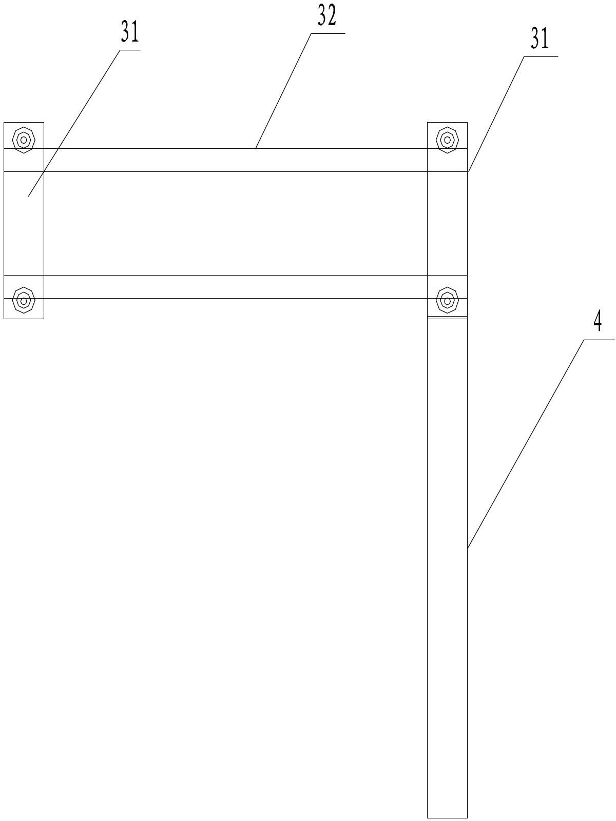
[0039] combine Figure 1 to Figure 4, in order to make the walking assembly 3 more stable during the movement, on the basis of Embodiment 1 or Embodiment 2, the walking assembly 3 preferably includes two groups of walking units 31, and the walking units include two slats 311, so The upper and lower ends of the two slats are respectively connected by the upper connecting shaft 312 and the lower connecting shaft 313, and the positions of the upper connecting shaft 312 and the lower connecting shaft 313 near the two slats 311 are respectively equipped with rollers 314, so The roller 314 of the upper connecting shaft 312 is in contact with the upper surface of the bracket 1, the roller 314 of the lower connecting shaft 313 is in contact with the lower surface of the bracket 1, and the wind-resistant assembly 4 is fixedly connected to one of them. Above the slats, the traction assembly 2 is fixedly connected to the traveling unit 31 , and the two traveling units 31 are connected th...


PUM


Abstract

The invention discloses a wind resisting device for a roller shutter door. The wind resisting device comprises a support, a traction component, a walking component and a wind resisting component, wherein the support is arranged on one side of the roller shutter door close to the inside of the door; a fixed pulley is arranged at a first end of the support; one end of the traction component is fixed on a winding shaft by winding, and the other end of the traction component is fixed on the walking component; the traction component crosses over the fixed pulley; the walking component is arranged on the support, can move relative to the support, moves to a first position of the support when the roller shutter door is opened, and can also move to a second position of the support when the roller shutter is opened; the first position is positioned at a second end of the support, and the second position is positioned in the middle of the support; and the wind resisting component is fixedly arranged on the walking component. The wind resisting device enhances the wind pressure resistance of the roller shutter door, so that gaps or damages are unlikely caused under the condition with strong wind.

Description

technical field [0001] The invention belongs to the field of doors and windows, in particular to a wind-resistant device for rolling shutter doors. Background technique [0002] The rolling door is mainly fixed by the surrounding frame. Since the rolling door is usually made of some metal strips connected to each other, due to the limitations of the structure and material properties of the rolling door itself, the wind resistance of the rolling door is relatively weak, especially in the industry. Due to the large height and width of the large rolling shutter door used, the plane bending resistance of the rolling shutter is also weak, and the surrounding frame is not enough to provide sufficient wind resistance for the rolling shutter door. When encountering strong winds, the rolling shutter door will be bent and deformed. Partial gaps are formed, and even the shutter door is destroyed. [0003] Therefore, how to solve the problem of wind pressure resistance of the rolling d...

Claims


Application Information

Patent Timeline
IPC IPC(8): E06B9/08E06B9/56
Inventor 陈为军
Owner HUNAN SHINILION ENERGY SAVING SCI & TECH
Why Eureka
Try Eureka