Method for manufacturing lamp strip having improvement on central point luminance of each backlight module

A backlight module and central technology, which is applied in the field of light bar production to improve the brightness of the central point of the backlight module, can solve the problems affecting the brightness of the central point of the backlight module, so as to ensure the brightness of the central point and the uniformity of illumination, and improve the optical grade , the effect of reducing production costs

Inactive Publication Date: 2012-09-26
TCL CHINA STAR OPTOELECTRONICS TECH CO LTD
View PDF5 Cites 8 Cited by
  • Summary
  • Abstract
  • Description
  • Claims
  • Application Information

AI Technical Summary

Problems solved by technology

[0003] see figure 1 , the existing backlight LED light bar includes a PCB board 100 and several LED lamps 200 installed on the PCB board 100. The several LED lamps 200 are LED lamps 200 of the same specification, such as 5630 or 7020 etc. These LED lamps 200 are not only of the same size, but also the materials such as crystal wires and chips inside the LED lamps 200 are also the same, and the adjacent spacing of the several LED lamps 200 is also fixed, which affects the use of the backlight to a certain extent. The central point brightness of the backlight module of the LED light bar

Method used


Image

  • Method for manufacturing lamp strip having improvement on central point luminance of each backlight module
  • Method for manufacturing lamp strip having improvement on central point luminance of each backlight module
  • Method for manufacturing lamp strip having improvement on central point luminance of each backlight module

Examples


Embodiment Construction

[0033] In order to further illustrate the technical means adopted by the present invention and its effects, the following describes in detail in conjunction with preferred embodiments of the present invention and accompanying drawings.

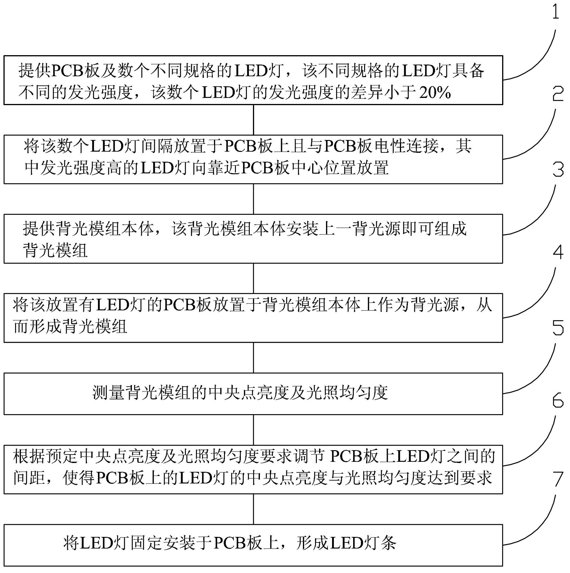
[0034] see Figure 2 to Figure 7 , the present invention provides a method for making a light bar for improving the brightness of the central point of a backlight module, comprising the following steps:

[0035] Step 1. Provide the PCB board 20 and several LED lamps 40 of different specifications. The LED lamps 40 of different specifications have different luminous intensities, and the difference of the luminous intensities of the several LED lamps 40 is less than 20%.

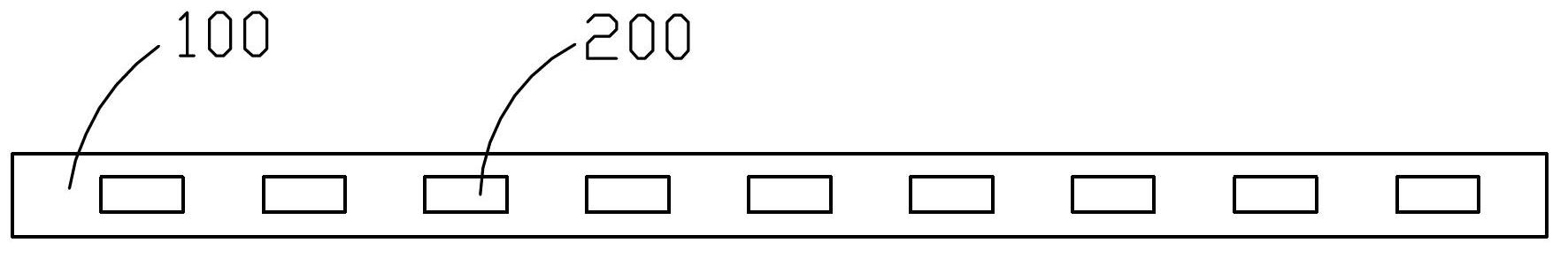
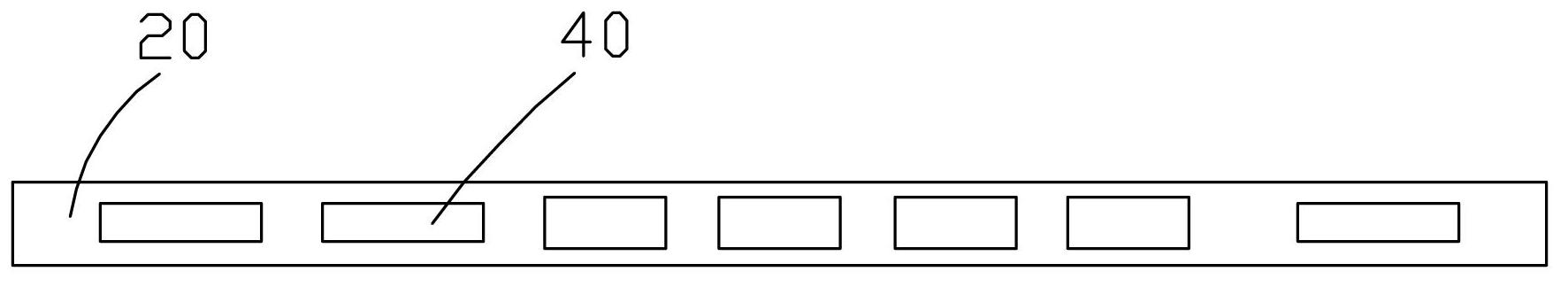
[0036] Described PCB board 20 is strip shape, and it can be a whole (as image 3 shown), it can also be spliced ​​by several PCB units, such as Figure 4 As shown, the PCB board 20 is formed by splicing two PCB units 22 and 24 .

[0037] The LED lamps 40 of different specif...


PUM


Abstract

The invention provides a method for manufacturing a lamp strip having an improvement on the central point luminance of each backlight module. The method comprises the steps as follows: step 1, providing a PCB (printed circuit board) and multiple different specifications of LED lamps having different luminous intensities, wherein the differences of the luminous intensities of the LED lamps are smaller than 20%; step 2, placing the LED lamps at intervals on the PCB, and electrically connecting the LED lamps with the PCB; step 3, providing a backlight module body, and mounting a backlight source on the backlight module body to form a backlight module; step 4, placing the PCB provided with the LED lamps on the backlight module body and using as a backlight source, so as to form a backlight module; step 5, measuring the central point luminance and illumination uniformity of each backlight module; step 6, regulating the distances between the LED lamps on the PCB according to preset central point luminance and illumination uniformity, and enabling the central point luminance and illumination uniformity of each LED lamp on the PCB to meet the requirements; and step 7, fixedly mounting the LED lamps on the PCB to form the LED lamp strip.

Description

technical field [0001] The invention relates to the field of liquid crystal displays, in particular to a method for manufacturing a light bar for improving the brightness of a central point of a backlight module. Background technique [0002] A liquid crystal display (LCD, Liquid Crystal Display) has many advantages such as a thin body, power saving, and no radiation, and has been widely used. Most of the liquid crystal display devices currently on the market are backlight liquid crystal displays, which include a liquid crystal display panel and a backlight module. The working principle of the liquid crystal display panel is to place liquid crystal molecules between two parallel glass substrates. There are many vertical and horizontal small wires between the two glass substrates. The direction of the liquid crystal molecules is controlled by electrifying or not, and the light of the backlight module Refracted out to produce a picture. Since the liquid crystal display panel...

Claims


Application Information

Patent Timeline
Patent Type & Authority Applications(China)
IPC IPC(8): F21S4/00F21V13/00F21V19/00G02F1/13357F21Y101/02
CPCG02B6/0068G02F1/133G02B6/0073G02F1/133603G02F1/133611
Inventor 胡哲彰张静
Owner TCL CHINA STAR OPTOELECTRONICS TECH CO LTD
Why Eureka
Try Eureka