
Backlight module

A backlight module and backplane technology, applied in the field of backlight modules, can solve the problems of insufficient glass substrate support, light leakage, large local stress, etc., and achieve the effect of improving the optical quality, increasing the supporting area, and preventing light leakage.

Inactive Publication Date: 2014-06-18
TCL CHINA STAR OPTOELECTRONICS TECH CO LTD
View PDF6 Cites 0 Cited by
  • Summary
  • Abstract
  • Description
  • Claims
  • Application Information

AI Technical Summary

Problems solved by technology

The split plastic frame (such as the four-corner plastic frame) has too much gap between the corner pieces 200 and insufficient support for the glass substrate, so that the entire glass is not evenly supported, resulting in excessive local stress, which has a great impact on the quality of the entire LCD module. In addition, if the gap between the corner parts is too large, there will be serious light leakage, which will affect the optical grade of the backlight module

Method used


Image

  • Backlight module
  • Backlight module
  • Backlight module

Examples


Embodiment Construction

[0023] In order to further illustrate the technical means adopted by the present invention and its effects, the following describes in detail in conjunction with preferred embodiments of the present invention and accompanying drawings.

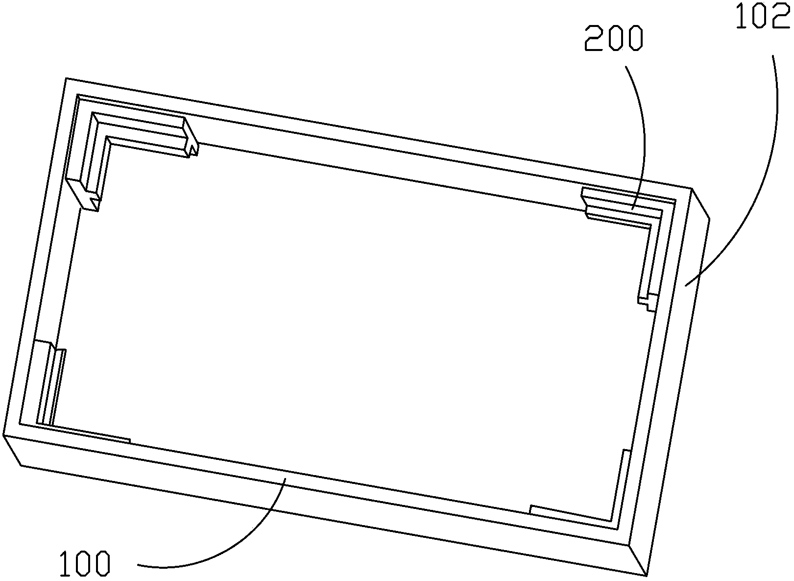
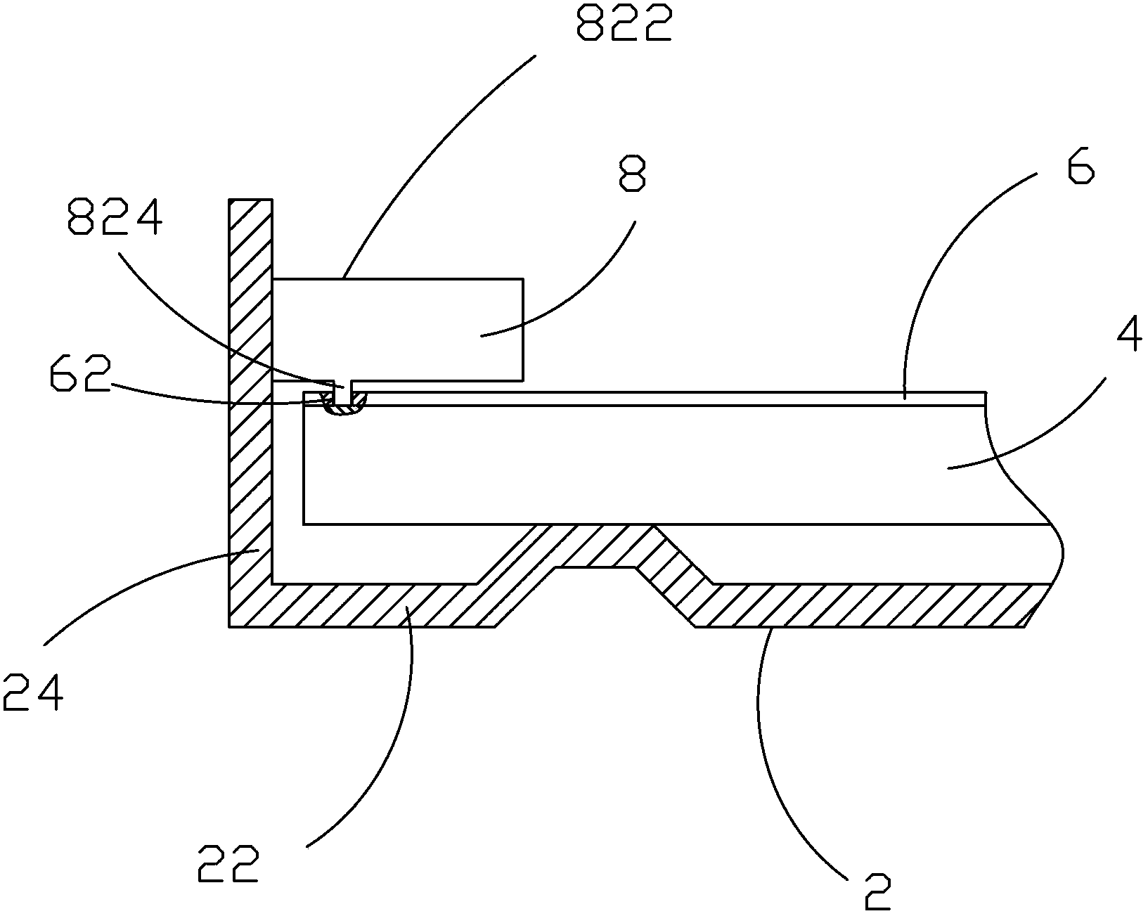
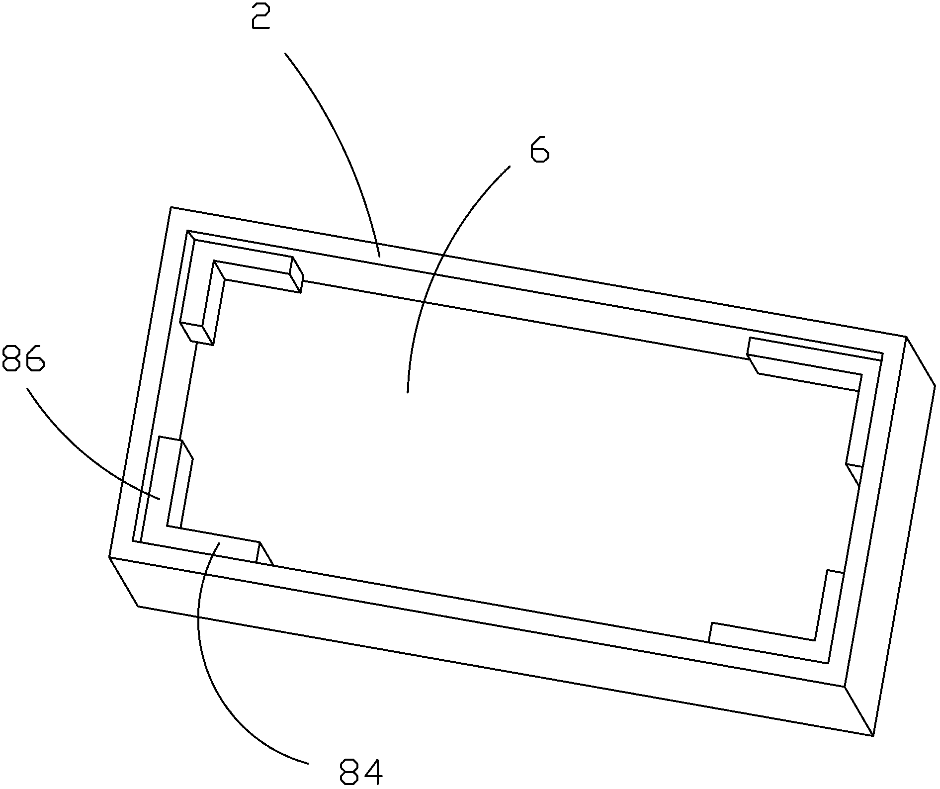
[0024] refer to figure 2 and image 3 , the present invention provides a backlight module, comprising: a backplane 2, a backlight source (not shown) arranged in the backplane 2, a light guide plate 4 arranged in the backplane 2, an optical The diaphragm set 6 and the split-type plastic frame 8 arranged in the back plate 2 , the split-type plastic frame 8 includes several separately arranged corner pieces 82 , which are respectively located on the optical film set 6 .

[0025] The backboard 2 includes a bottom board 22 and a plurality of side boards 24 connected to the bottom board 22 , and the corner pieces 82 are respectively installed on the side boards 24 of the back board 2 by gluing or screwing. Preferably, the corner pieces 82 are res...


PUM


Abstract

A backlight module comprising a back panel (2), a backlight source arranged within the back panel (2), a light-guide plate (4) arranged within the back panel (2), an optical film set (6) arranged on the light-guide plate (4), and a split-body-type plastic frame (8) arranged within the back panel (2). The split-body-type plastic frame (8) comprises several separately arranged corner pieces (82), which respectively are arranged on the optical film set (6). The corner pieces (82) are provided away from the optical film set (6) with support surfaces (822) used for supporting a liquid crystal display panel. By employing the upper surfaces of the split-body-type plastic frame (8) as the support surfaces (822) for the liquid crystal display panel, the backlight module enlarges the area for supporting the liquid crystal display panel, thus improving the support stability, effectively preventing a light-leakage phenomenon from occurring, ensuring the luminance of the backlight module, and increasing optical grade.

Description

technical field [0001] The invention relates to the field of liquid crystal display, in particular to a backlight module. Background technique [0002] A liquid crystal display (LCD, Liquid Crystal Display) has many advantages such as a thin body, power saving, and no radiation, and has been widely used. Most of the liquid crystal display devices currently on the market are backlight liquid crystal display devices, which include a liquid crystal display panel and a backlight module. The working principle of the liquid crystal display panel is to place liquid crystal molecules between two parallel glass substrates. There are many vertical and horizontal small wires between the two glass substrates. The direction of the liquid crystal molecules is controlled by electrifying or not, and the light of the backlight module Refracted out to produce a picture. Since the liquid crystal display panel itself does not emit light, the light source provided by the backlight module is ne...

Claims


Application Information

Patent Timeline
Patent Type & Authority Patents(China)
IPC IPC(8): G02F1/13357F21S8/00F21V17/12F21V17/10
CPCG02F2001/133328G02F1/133308G02B6/0088G02F2001/133317G02F1/133317G02F1/133328
Inventor 郭仪正陈仕祥俞刚周革革王甲强
Owner TCL CHINA STAR OPTOELECTRONICS TECH CO LTD
Learn More