

Automatic traceless fusion welding technology of thin-wall stainless steel clean pipeline
A stainless steel and pipeline technology, which is applied in the field of automatic traceless fusion welding process for thin-walled stainless steel clean pipelines, can solve the problems of difficult control of pipeline cleanliness, poor cleanliness control effect, and poor internal and external welding seam forming, so as to ensure cleanliness and smoothness. Brightness, saving argon consumption, fast welding speed
- Summary
- Abstract
- Description
- Claims
- Application Information
AI Technical Summary
Problems solved by technology
Method used
Image

Examples
Embodiment 1
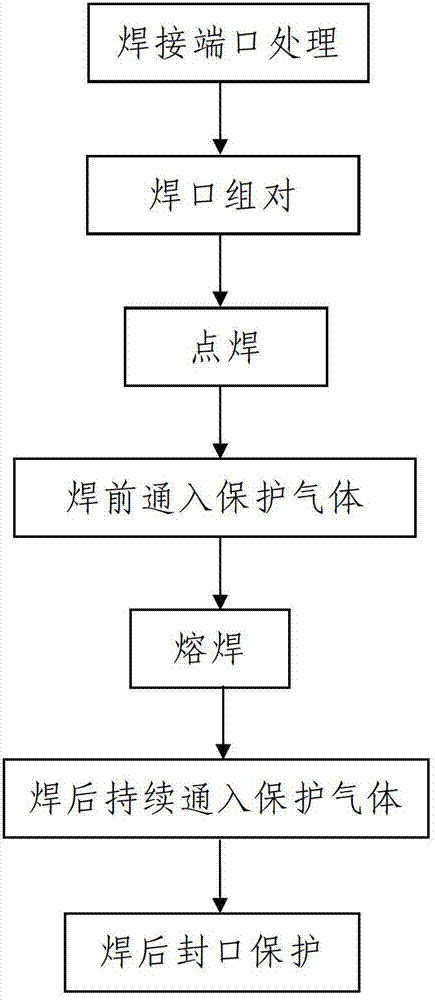
[0042] Such as figure 1 An automatic non-mark welding process for a thin-walled stainless steel clean pipeline includes the following steps:
[0043] Step 1. Welding port treatment: milling the welded faces of the pipe ends of the two pipe sections to be welded into a plane; the two pipe sections are stainless steel pipes, and the outer diameter and wall thickness of the two pipe sections are They are all the same, and the outer diameter of the pipe segment is Φ6.3mm˜Φ190.5mm and its wall thickness is not greater than 3mm.
[0044] In this embodiment, the outer diameters of the two pipe segments are Φ16mm˜Φ18mm and the wall thickness is 0.64mm.
[0045] Before the actual welding port treatment, the pipe segment to be welded needs to be prefabricated, and the prefabrication process must be carried out in a clean room. The purpose of the prefabrication is to minimize the welding workload on site. The pipeline section must be sealed with clean plastic before and after processin...
Embodiment 2
[0090] In this embodiment, the difference from Embodiment 1 is that the argon gas supply device described in step 3 has a gas flow rate of 5 L / min; when welding in step 402, the argon tungsten arc welding machine The protruding length of the tungsten electrode is d1=0.8mm, and the distance between the front end of the tungsten electrode and the welding position is d2=0.8mm. The arc length of the argon tungsten arc welding machine is preferably 0.74mm. The rotation speed is 6.0rpm and the welding time is 13s; in step 401, step 402 and step 403, the gas flow rate of the argon gas supply into the argon gas supply equipment is 5L / min, and the argon gas supply equipment into the argon gas The flow rate is 25mm / s, and t1=t2=15s.
[0091] In this embodiment, the remaining process steps and process parameters are the same as those in Example 1.
Embodiment 3
[0093] In this embodiment, the difference from Embodiment 1 is that: the argon gas supply equipment described in step 3 has a gas flow rate of 14 L / min; when welding in step 402, the gas tungsten arc welding machine The protruding length of the tungsten electrode is d1=1.2mm, and the distance between the front end of the tungsten electrode and the welding position is d2=1.2mm. The arc length of the argon tungsten arc welding machine is preferably 0.78mm. The rotation speed is 7.2rpm and the welding time is 10s; in step 401, step 402 and step 403, the gas flow rate of the argon gas supply into the argon gas supply equipment is 14L / min, and the argon gas supply equipment into the argon gas The flow rate is 35mm / s, and t1=t2=25s.
[0094] In this embodiment, the remaining process steps and process parameters are the same as those in Example 1.
PUM
| Property | Measurement | Unit |
|---|---|---|
| Outer diameter | aaaaa | aaaaa |
| Thickness | aaaaa | aaaaa |
| Outer diameter | aaaaa | aaaaa |
Abstract
Description
Claims
Application Information