Needle bed structure of computerized flat knitting machine

A technology of flat knitting machines and needle beds, which is applied in knitting, weft knitting, textiles and papermaking, etc. It can solve problems such as difficulty in guaranteeing the quality of knitted fabrics and the influence of knitting needle movement stability, so as to improve motion stability and ensure knitting effect of effect

Inactive Publication Date: 2012-10-03
JIANGSU JINLONG TECHNOLOGY CO LTD
View PDF5 Cites 2 Cited by
  • Summary
  • Abstract
  • Description
  • Claims
  • Application Information

AI Technical Summary

Problems solved by technology

[0003] As can be seen from the above structure, since the insertion strip 121 must be configured, the insertion strip groove 12 cannot be avoided, because if the insertion strip 121 is removed, the knitting needle assembly will be lost. the tube bundle, which can cause undesirable parts such as broken needles and damage to the triangle on the head plate of the handpiece
More specifically, if the insert 121 is missing, knitting

Method used


Image

  • Needle bed structure of computerized flat knitting machine
  • Needle bed structure of computerized flat knitting machine
  • Needle bed structure of computerized flat knitting machine

Examples


Embodiment Construction

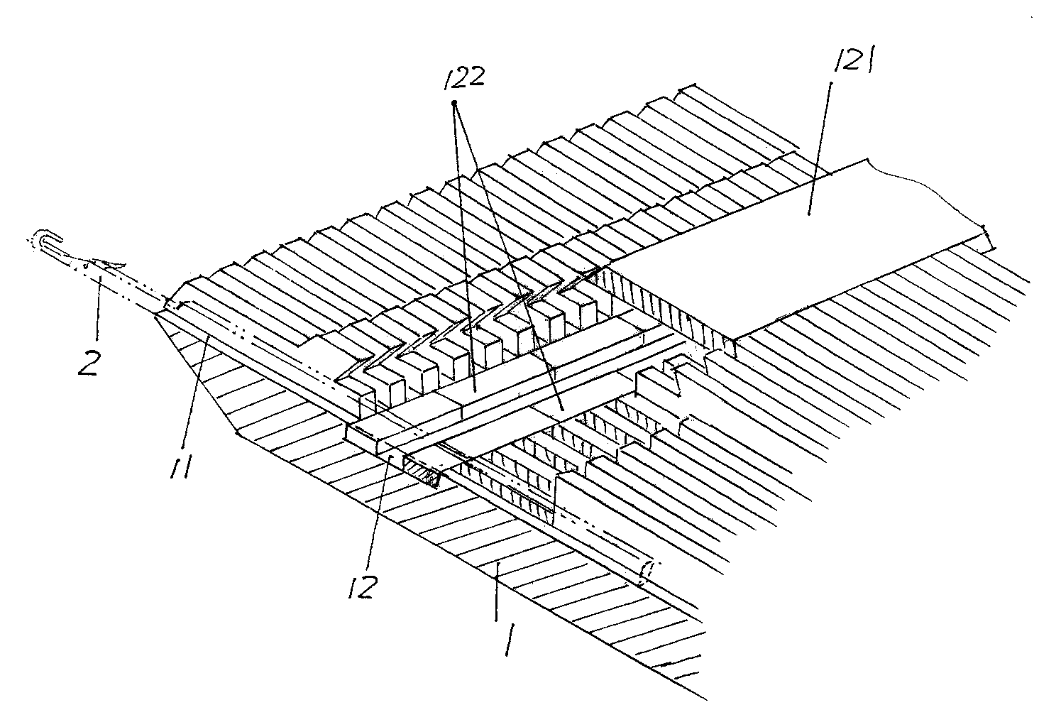
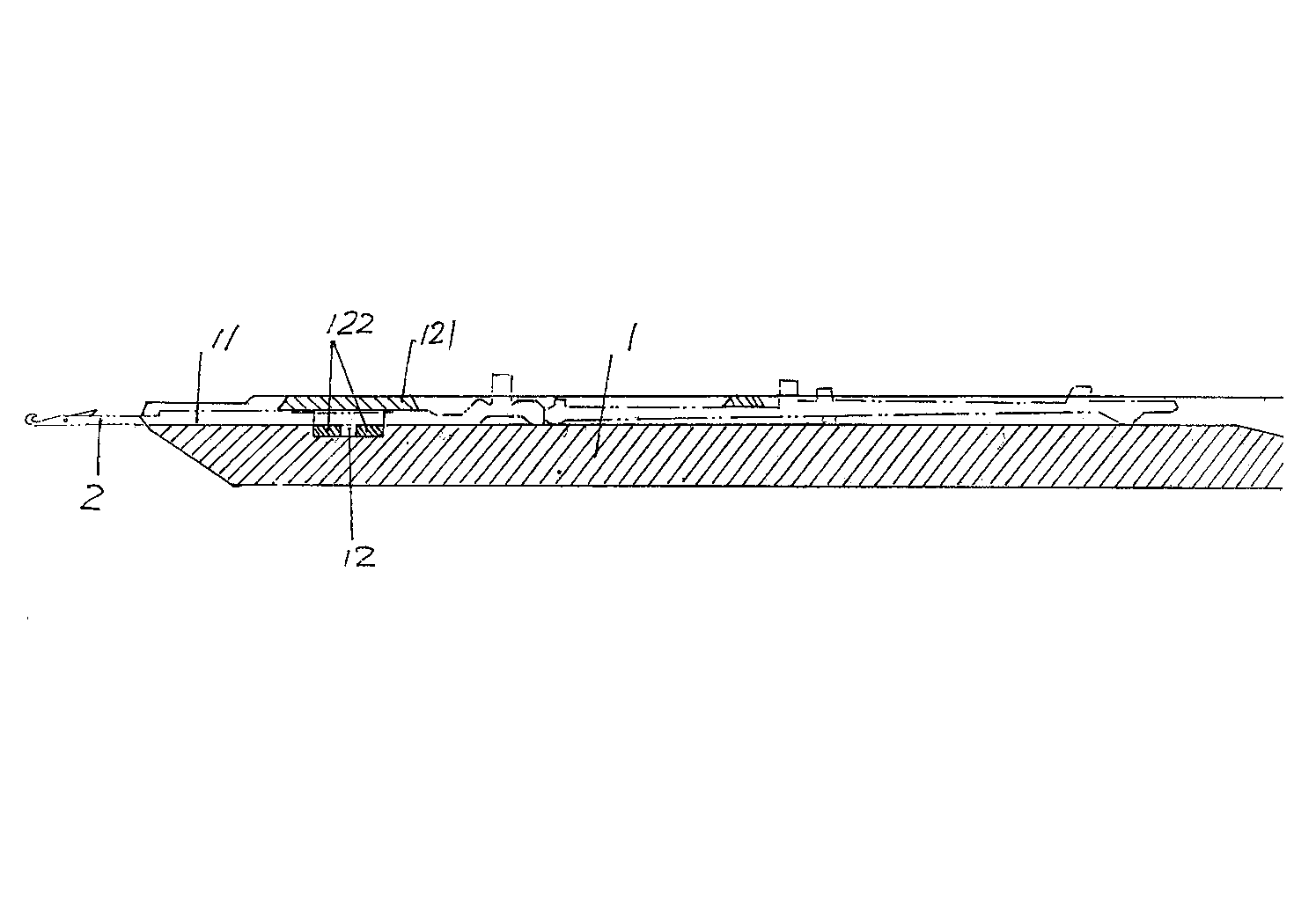
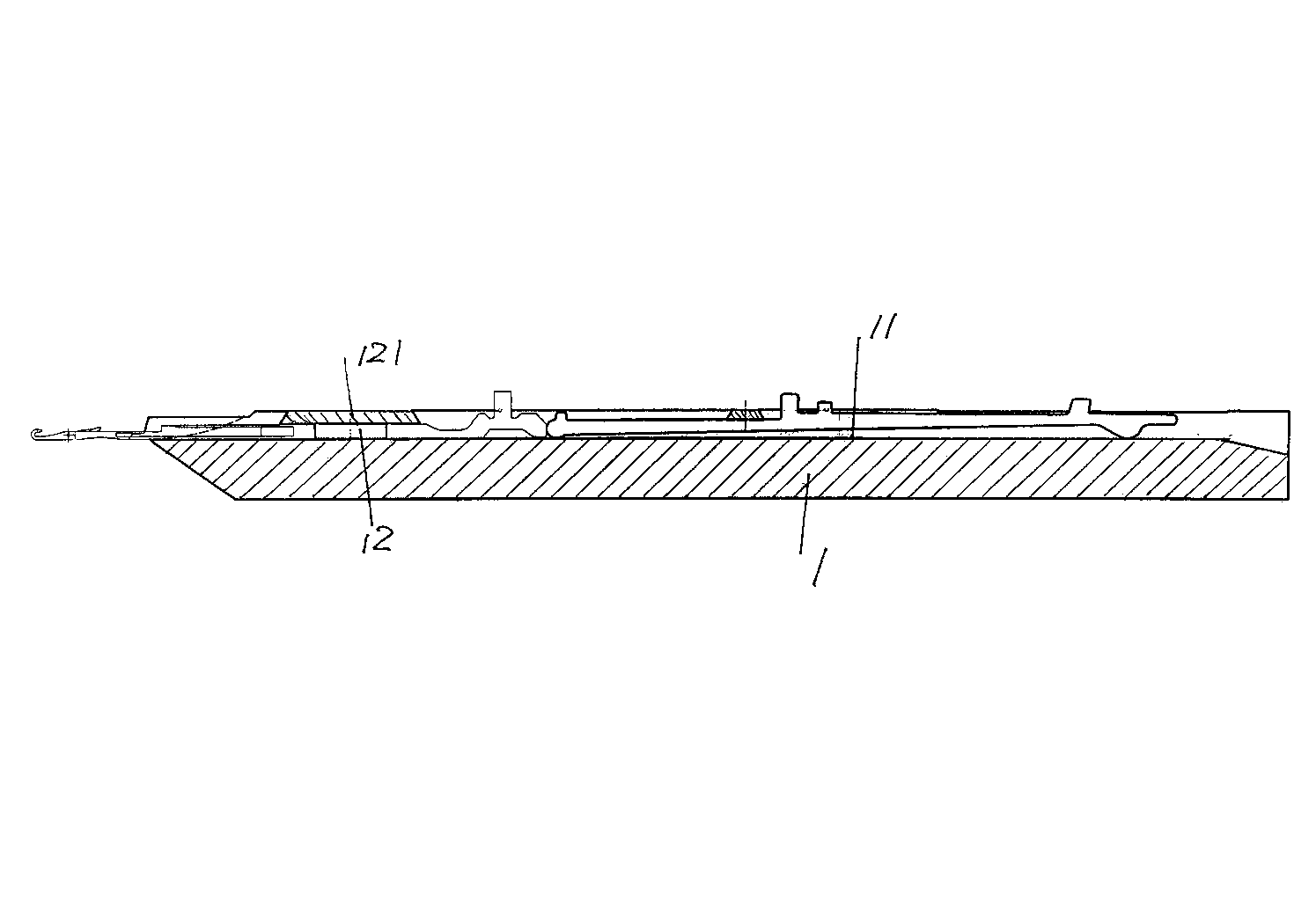
[0013] See figure 1 and figure 2 , a needle bed body 1 is given, the length direction of the needle bed body 1 is provided with needle grooves 11 equal to the number of knitting needles 2 of the knitting needle assembly described above in a spaced state from one end to the other end, each A knitting needle 2 is movablely arranged in a needle groove 11. In the state of use, the needle groove 11 faces the side of the head of the knitting mechanism of the computerized flat knitting machine, that is, it is in the figure 1 and figure 2 status shown. An insertion strip groove 12 is also provided on the needle bed body 1, and the insertion strip groove 12 forms a cross-shaped staggered relationship with the aforementioned needle groove 11, and an insertion strip 121 is inserted in the insertion strip groove 12, and the insertion strip 121 Also known as grating or layering.

[0014] Since there is a cavity between the bottom of the insertion strip groove 12 and the inse...


PUM


Abstract

The invention discloses a needle bed structure of a computerized flat knitting machine, and belongs to the technical field of knitting machinery. The needle bed structure comprises a needle bed body, a group of needle grooves and at least one insert groove are formed in an area from one end of the needle bed body to the other end at intervals in the length direction and form a cross relation, and an insert is inserted into the insert groove. The needle bed structure is characterized in that magnetic stripes are arranged at the bottom of the insert groove and in the length direction of the insert groove, the lower parts of knitting needles of a knitting needle assembly attract the magnetic stripes, and the upper parts of the knitting needles are in contact with the insert. The needle bed structure has the advantages that the magnetic stripes are arranged at the bottoms of the needle grooves, and the magnetic stripes attract the knitting needles of the knitting needle assembly, so that moving stability of the knitting needles in the needle grooves can be remarkably improved, and the knitting effect of a knitting mechanism is ensured.

Description

technical field [0001] The invention belongs to the technical field of knitting machinery, and in particular relates to a needle bed structure of a computerized flat knitting machine. Background technique [0002] image 3 Shown is the needle bed structure of the computerized flat knitting machine commonly used in the prior art, including the needle bed body 1, and the needle bed body 1 facing the head of the knitting mechanism is provided with a needle bed for inserting the needle bed in the use state. A group of needle slots 11 of the needle assembly, and at least one insertion slot 12 is provided, the insertion slot 12 forms a cross-staggered relationship with the needle slot 11, and insertion strips 121 are inserted on the insertion slots 12, by insertion strips 121 acts as a needle stop for the knitting needle assembly that is located in the needle groove 11 and can move back and forth. [0003] Known by above-mentioned structure, because inserting strip 121 is necessa...

Claims


Application Information

Patent Timeline
IPC IPC(8): D04B15/10
Inventor 金永良付洪平兰先川
Owner JIANGSU JINLONG TECHNOLOGY CO LTD
Why Eureka
Try Eureka