
Pushing device

A push device and push plate technology, which is applied in the direction of layered products, metal layered products, and equipment for handling casting molds, can solve problems such as vibration, shaking, tilting, unstable movement, and molten iron leakage of mold loading vehicles. To achieve the effect of improving motion stability, simple structure, reducing vibration and noise

Inactive Publication Date: 2020-07-17
惠州典展五金制品有限公司
View PDF0 Cites 2 Cited by
  • Summary
  • Abstract
  • Description
  • Claims
  • Application Information

AI Technical Summary

Problems solved by technology

However, if the cylinder is used for a long time, air leakage will occur, the temperature will rise, and the air pressure will be unstable. In the process of pushing the mold loading vehicle, the pressure will continue to increase, the movement will be unstable, and even the push rod of the cylinder will suddenly accelerate and "rush out". , causing the mold loading vehicle to vibrate, shake, tilt, etc., resulting in the leakage and splashing of molten iron in the mold loaded on the mold loading vehicle and hurting people

Method used


Image

  • Pushing device
  • Pushing device
  • Pushing device

Examples


Embodiment Construction

[0029] In order to facilitate the understanding of the present invention, the present invention will be described more fully below with reference to the associated drawings. Preferred embodiments of the invention are shown in the accompanying drawings. However, the present invention can be embodied in many different forms and is not limited to the embodiments described herein. On the contrary, the purpose of providing these embodiments is to make the disclosure of the present invention more thorough and comprehensive.

[0030] It should be noted that when an element is referred to as being “fixed” to another element, it can be directly on the other element or there can also be an intervening element. When an element is referred to as being "connected to" another element, it can be directly connected to the other element or intervening elements may also be present. The terms "vertical," "horizontal," "left," "right," and similar expressions are used herein for purposes of ill...


PUM


Abstract

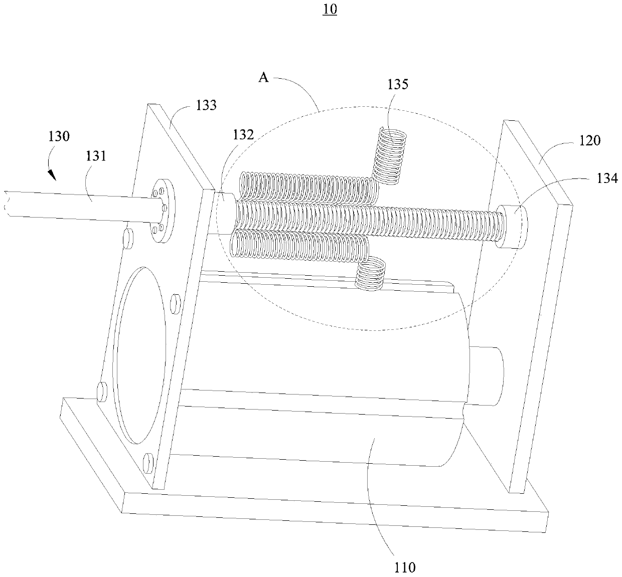
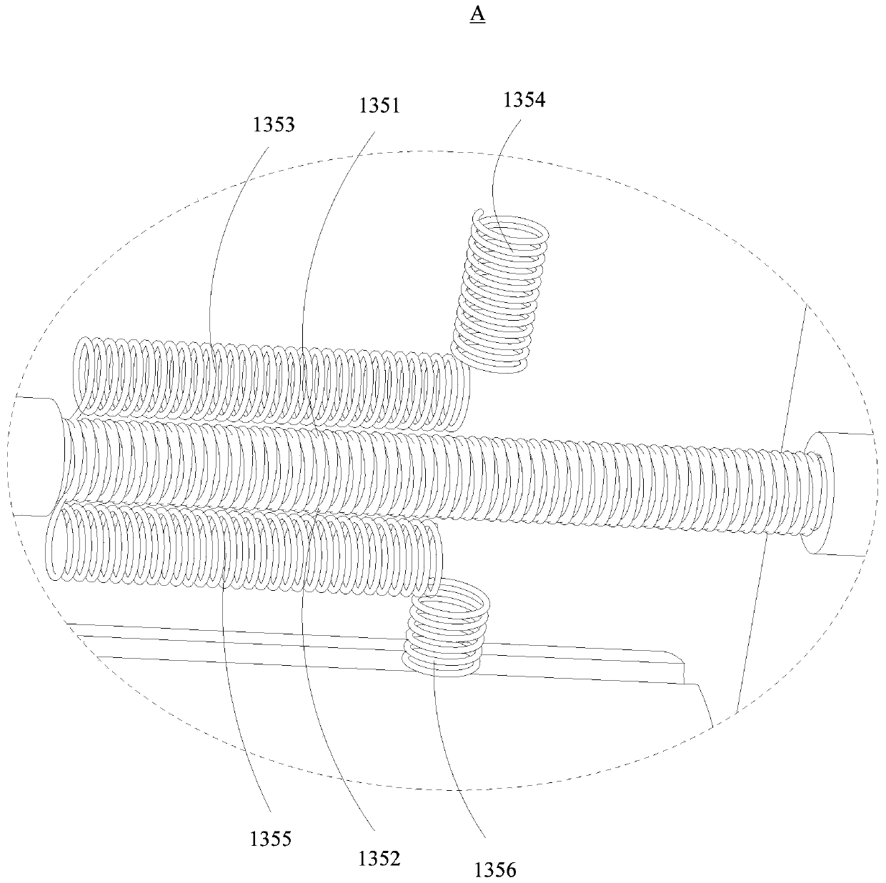
The invention relates to the field of mold processing, and discloses a pushing device. The pushing device comprises a driving cylinder, a pushing plate and a guiding assembly. A pushing rod of the driving cylinder is connected with the pushing plate. The guiding assembly comprises a guiding shaft, a linear bearing, a fixing plate, a fixing sleeve, a sealing ring and a spring structure. The drivingcylinder is connected with the first end of the fixing plate. The second end of the fixing plate is connected with the linear bearing. The linear bearing sleeves the guiding shaft. One end of the guiding shaft is connected with the pushing plate through the fixing sleeve. The sealing ring is arranged between the fixing sleeve and the guiding shaft. The spring structure sleeves the guiding shaft and is located between the fixing plate and the pushing plate. The pushing device has the advantages of being simple in structure, reliable in work and stable in motion, can accurately and stably pusha mold loading vehicle to prevent vibration, shaking, tilting and the like of the mold loading vehicle.

Description

technical field [0001] The invention relates to the field of mold processing, in particular to a pushing device. Background technique [0002] Mold processing refers to the processing of forming and billet tools, and also includes shearing dies and die-cutting dies. Usually, the mold consists of two parts, the upper mold and the lower mold. The molten iron is poured between the upper and lower molds, and the material is formed under the action of the press. When the press is opened, the workpiece determined by the shape of the mold will be obtained or the corresponding waste will be removed. Workpieces as small as electronic connectors and as large as automotive dashboards can be molded. Progressive die refers to a set of molds that can automatically move the workpiece from one station to another, and obtain formed parts at the last station. Mold processing technology includes: cutting die, punching die, composite die, extrusion die, four slide rail die, progressive die, ...

Claims


Application Information

Patent Timeline
Patent Type & Authority Applications(China)
IPC IPC(8): B22D33/02B32B1/08B32B3/08B32B3/26B32B3/30B32B5/02B32B15/08B32B15/088B32B15/09B32B15/18B32B15/20B32B33/00
CPCB22D33/02B32B1/08B32B3/08B32B3/266B32B3/30B32B5/028B32B15/08B32B15/088B32B15/09B32B15/18B32B15/20B32B33/00B32B2250/04B32B2307/202B32B2307/206B32B2307/3065B32B2307/308B32B2307/54B32B2307/554B32B2307/558B32B2307/714
Inventor 付国友
Owner 惠州典展五金制品有限公司
Learn More