
Striker plate for paver and paver

A material retaining board and paver technology, applied to roads, road repairs, roads, etc., can solve problems such as difficult connection and positioning, complex structure, and poor material retaining effect

Inactive Publication Date: 2012-10-03
ZOOMLION HEAVY IND CO LTD
View PDF9 Cites 16 Cited by
  • Summary
  • Abstract
  • Description
  • Claims
  • Application Information

AI Technical Summary

Problems solved by technology

However, there are certain defects in these two schemes. For the oil cylinder adjustment mechanism, it is necessary to install and design a matching hydraulic system to realize the function of lifting and lowering the baffle. The structure is more complicated and the cost is higher. The connection and positioning between the rear panels of the main engine are difficult, complicated, and inconvenient to operate; the use of flexible auxiliary baffles is not effective in blocking materials. The higher the bottom surface of the baffle is from the ground, the higher the material accumulation will be. The blocking effect is worse

Method used


Image

  • Striker plate for paver and paver
  • Striker plate for paver and paver
  • Striker plate for paver and paver

Examples


Embodiment Construction

[0039] Specific embodiments of the present invention will be described in detail below in conjunction with the accompanying drawings. It should be understood that the specific embodiments described here are only used to illustrate and explain the present invention, and are not intended to limit the present invention.

[0040] In the present invention, unless stated otherwise, the used orientation words such as "up and down" are usually relative to figure 2 In terms of the height direction shown, "left, right" is usually relative to such as figure 2 In terms of the length direction shown, "front and rear" are usually relative to figure 2 In the width direction shown.

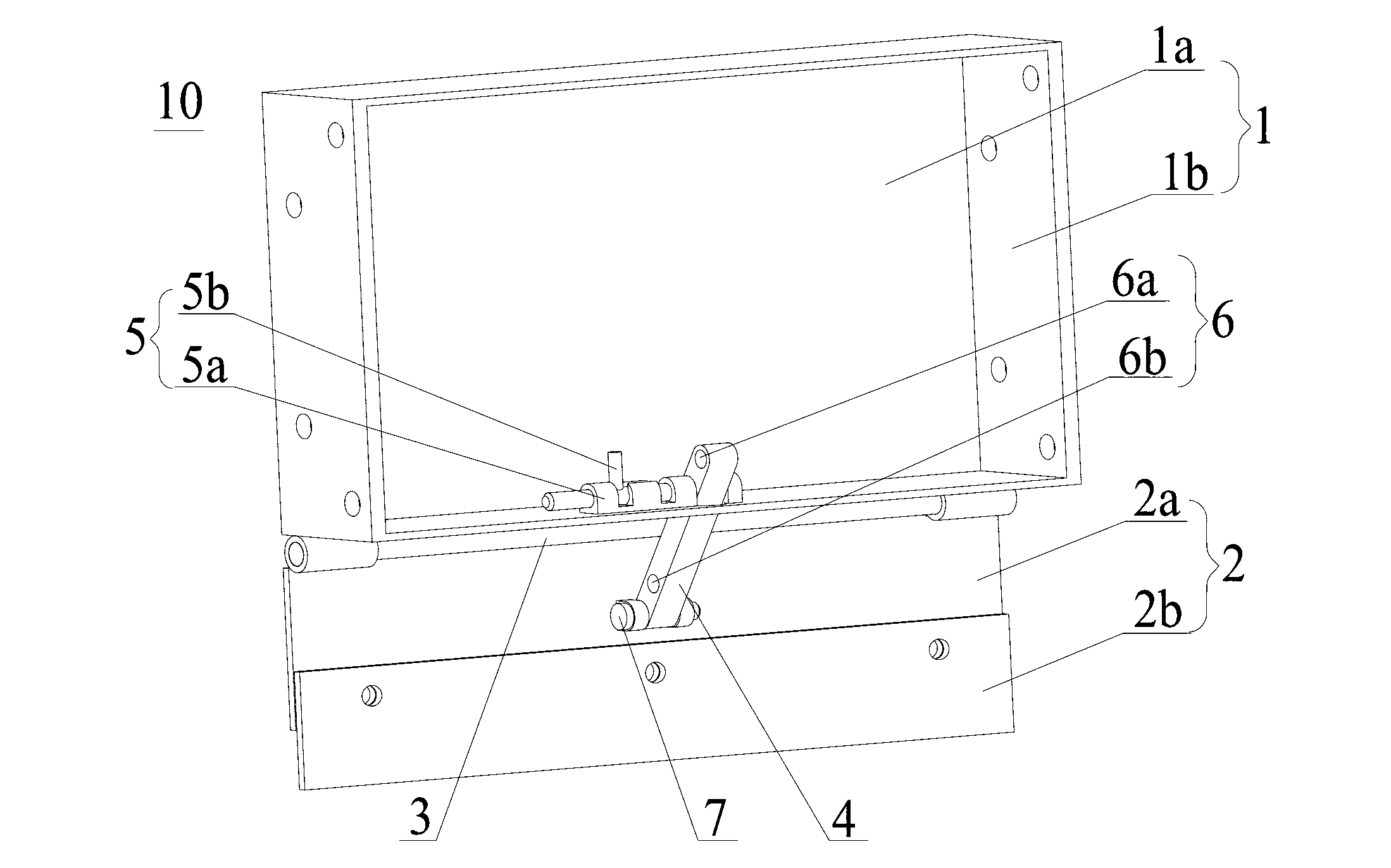
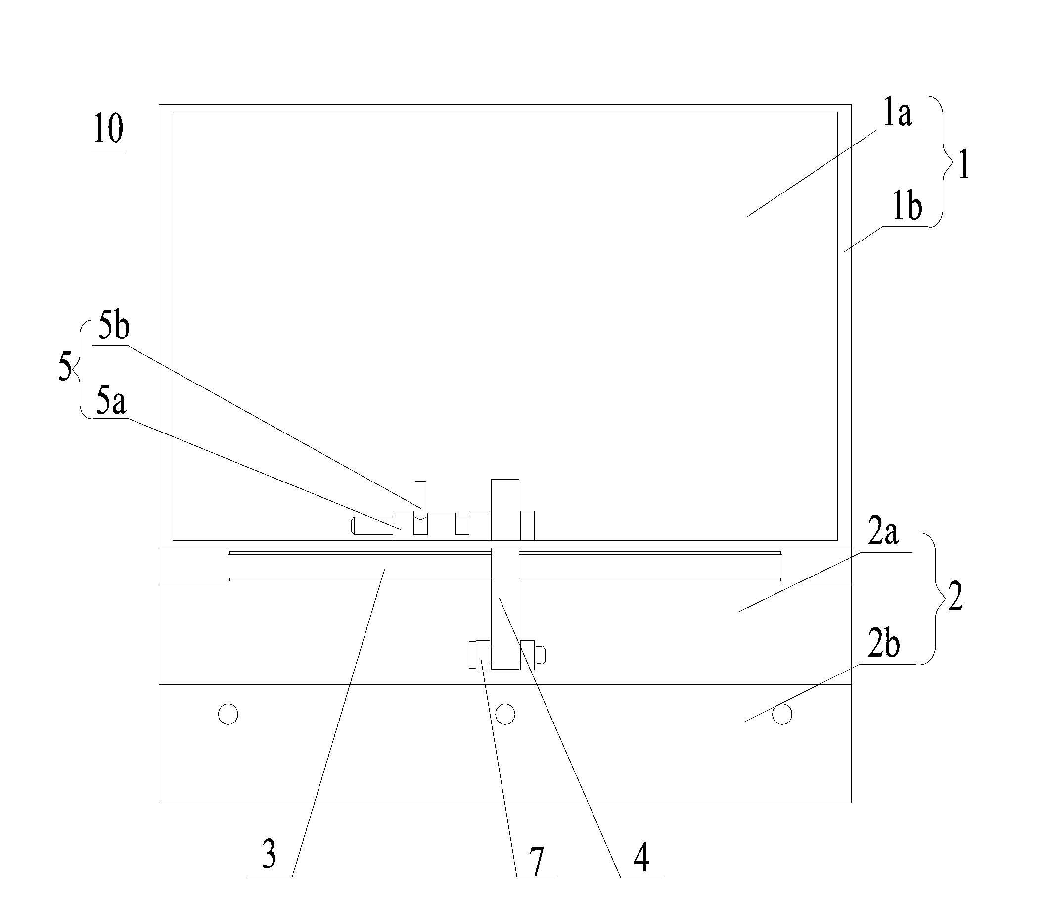
[0041] Such as Figure 2-Figure 6 As shown, one aspect of the present invention provides a material baffle 10 of a paver, wherein the material baffle 10 includes a fixed baffle 1 and a movable baffle 2, and the movable baffle 2 is rotatably connected to the The lower end of the baffle 1 is fixed to adjust ...


PUM


Abstract

The invention discloses a striker plate (10) for a paver, wherein the striker plate (10) comprises a fixed baffle plate (1) and a movable baffle plate (2); and the movable baffle plate (2) is rotatably connected on the lower end of the fixed baffle plate (1) so as to adjust the integral height of the striker plate (10). The invention further discloses a paver. The integral height of the striker plate is adjustable so as to be adapted to operating requirements of the paver under different working conditions, so that the materials can be prevented from falling and separating to ensure paving quality.

Description

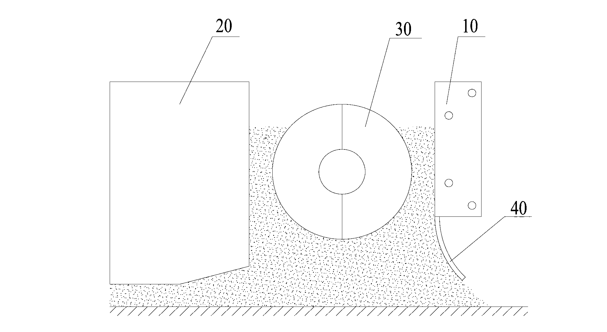
technical field [0001] The invention relates to the field of engineering machinery, in particular to a material retaining plate of a paver and the paver. Background technique [0002] The working principle of the paver is that the material is unloaded from the dump truck into the hopper of the paver, and transferred to the paving room through the scraper conveyor, and the material is spread horizontally by the spiral distribution mechanism in the paving room. With the running of the paver, the spread material falls from the paving room to the road surface, and is preliminarily compacted by the vibrator, and then the screed behind it is trimmed to an appropriate thickness according to the designed paving thickness. Cross-section and ironed. [0003] Currently, if figure 1 As shown, the screw distribution mechanism of the paver mainly includes a screw push rod 30, a material baffle plate 10, a pull rod and a guardrail, etc., wherein the pull rod and the guard rail are not sh...

Claims


Application Information

Patent Timeline
IPC IPC(8): E01C19/48
Inventor 徐仁建罗海斌
Owner ZOOMLION HEAVY IND CO LTD
Learn More