
Roadbed slab non-tensile stress construction method based on combined channel girder

A construction method and technology of combined troughs, which are applied in the directions of bridges, bridge construction, erection/assembly of bridges, etc., can solve the problems affecting vehicle traffic under the bridge and the urban environment, high requirements for hoisting and transportation capacity, and difficult layout of structural prestressed beams, etc. problems, to achieve the effect of reducing the amount of on-site work, shortening the construction period, and making the structure light.

Inactive Publication Date: 2015-03-11
SOUTHEAST UNIV
View PDF11 Cites 0 Cited by
  • Summary
  • Abstract
  • Description
  • Claims
  • Application Information

AI Technical Summary

Problems solved by technology

[0003] However, the channel beam belongs to the composite structure of the bottom plate beam, and the central axis of the section is relatively low, resulting in a low efficiency of the longitudinal prestress to generate the resistance bending moment. Generally, a large number of prestress beams need to be configured, which makes the arrangement of the structural prestress beam difficult. , poor structural durability
[0004] At present, most of the existing channel girders adopt the construction method of pouring in situ with full support. This method needs to set up full support to level and reinforce the foundation under the bridge, thus affecting the traffic of vehicles under the bridge and the urban environment, and the resulting damage The disadvantages of heavy construction workload, long period, and high cost; however, the existing overall prefabricated hoisting or main girder prefabricated hoisting construction methods have high requirements for hoisting and transportation capabilities
These problems have caused certain difficulties to the application and popularization of channel beams.

Method used


Image

  • Roadbed slab non-tensile stress construction method based on combined channel girder
  • Roadbed slab non-tensile stress construction method based on combined channel girder
  • Roadbed slab non-tensile stress construction method based on combined channel girder

Examples


Embodiment Construction

[0025] The accompanying drawings disclose, without limitation, the structural schematic diagrams of the preferred embodiments involved in the present invention; the technical solution of the present invention will be described in detail below in conjunction with the accompanying drawings.

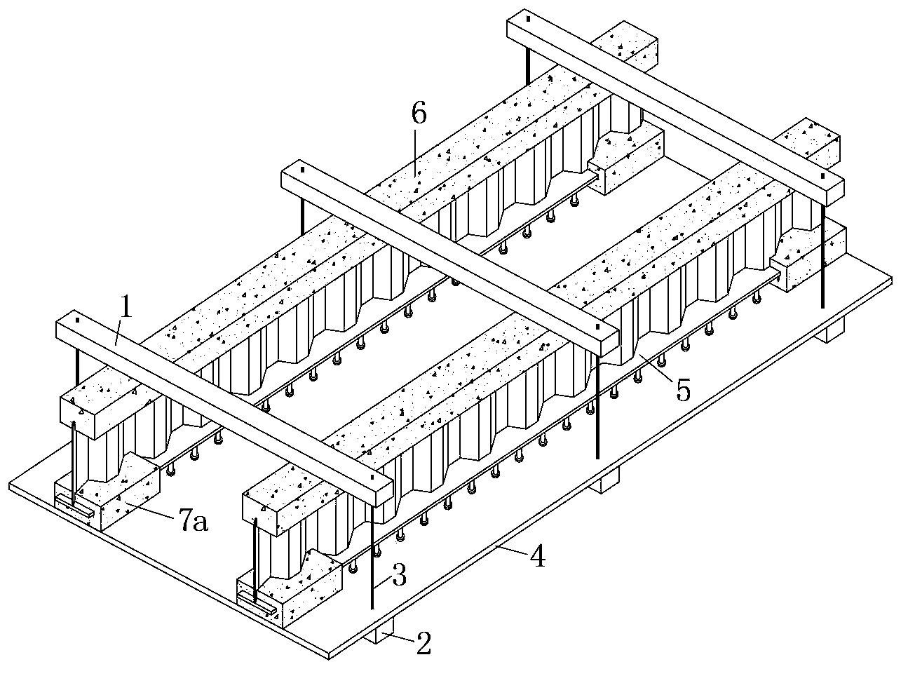
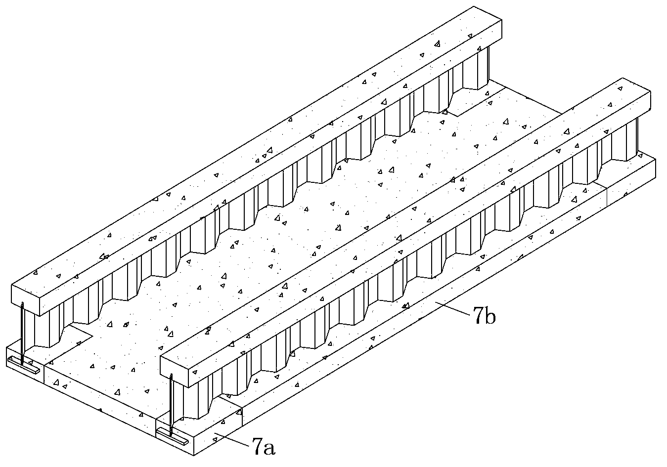
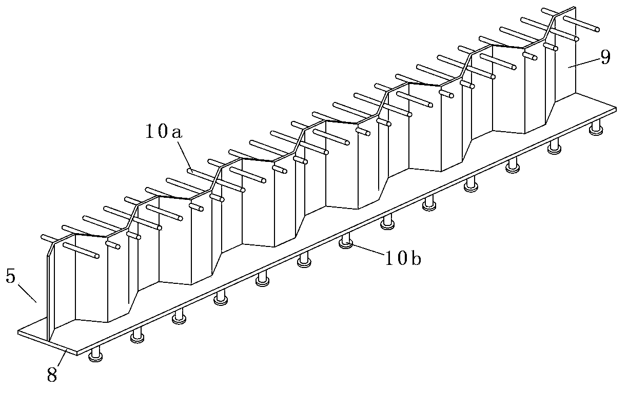
[0026] The following is attached Figure 1-5 , further describe the implementation process of the present invention:

[0027] A. Steel web 9 is welded on steel bar 8 to form steel girder 5, such as Figure 5 As shown in (a), the cross-sectional size and pre-arch value of the steel bar 8 should be determined according to the structural self-weight of the channel beam; this step can be welded and assembled in the factory; the steel web is a corrugated steel plate or a flat steel plate, of which Corrugated steel plates do not need to be equipped with structural measures to prevent roll instability, while flat steel plates need to be provided with stud shear connectors on the surface, and the...


PUM


Abstract

The invention discloses a roadbed slab non-tensile stress construction method based on a combined channel girder, which includes the following steps: A, manufacturing combined I beams by firstly manufacturing steel beams, and carrying out first-stage concrete casting for the upper flanges and the lower flanges of the steel beams in a precast yard, so as to correspondingly form the upper flange plates and the first-stage concrete blocks of the roadbed slab and then accomplish the manufacturing of the combined I beams; B, hoisting the two groups of combined I beam manufactured and formed according to the step A in the construction site as required by the to-be-manufactured combined channel girder; C, taking the combined I beams hoisted according to the step B as a support mounting hoisting mold; and D, carrying out the roadbed slab second-stage concrete casting for the lower flanges of the combined I beams, so as to accomplish the manufacturing of the combined channel girder. The combined I beams manufactured according to the step A mainly bears the load through the stress on the upper flange concrete plates and tensile force on the lower flange steel bars, so as to realize the function of the beam.

Description

technical field [0001] The invention relates to a construction method for a steel-concrete composite bridge structure, in particular to a construction method for casting-in-place hanging formwork for a composite groove-shaped girder bed slab, and belongs to the technical field of bridge structures. Background technique [0002] Channel girders, also known as U-shaped girders, were first studied abroad in the early 20th century, and were first applied to Rocherham Bridge in England in 1952. Since then, it has been used many times in bridge projects in Japan, France, Germany and other countries. my country began to study it in the late 1970s, and in 1982, the first double-track railway channel beam was built near the Huairou Station of the Beijing-Chengdu (Germany) Line, and was subsequently used in rail transit and highway bridges many times. Practice and research have shown that the channel beam has the advantages of low building height and low noise, and is a bridge struct...

Claims


Application Information

Patent Timeline
Patent Type & Authority Patents(China)
IPC IPC(8): E01D21/00
Inventor 黄侨陈卓异杨明马文刚
Owner SOUTHEAST UNIV
Learn More