Fiber reinforced composite material cable trough

A composite material and fiber-reinforced technology, which is applied in the installation of cables and cables in ground conduits, etc., can solve the problems of heavy maintenance and repair work, no constraints, and lateral instability of plates, so as to improve the resistance to longitudinal and The ability to bend laterally, improve the ability to resist longitudinal bending, and prevent roll instability

Inactive Publication Date: 2019-12-03
RAILWAY ENG RES INST CHINA ACADEMY OF RAILWAY SCI +2
View PDF12 Cites 0 Cited by
  • Summary
  • Abstract
  • Description
  • Claims
  • Application Information

AI Technical Summary

Problems solved by technology

These three types of cable ducts only restrict the outward deformation of the top of the side plate of the trough, but they do not restrain its inward deformation. The plate with a free upper end is prone to lateral instability and warping. Once the inward deformation is too If it is too large, the boss or right-angle hook at the top of the side plate of the tank body will lose its effect
In addition, when the maintenance and repair personnel occasionally step on the cover of the cable trough or the bottom plate of the trough body, the cover and the bottom plate of the trough body will be deformed downward, such as Figure 5 and Image 6 As shown, the side plate of the tank body will be deformed inward, and this deformation cannot be recovered sometimes
If there is downward irreversible deformation of the tank cover, it is easy to accumulate water, which will affect the durability of the tank cover
[0004] If the material of the cable tray is steel plate, it is easy to rust, and needs to be painted regularly, and the maintenance and repair workload is heavy

Method used


Image

  • Fiber reinforced composite material cable trough
  • Fiber reinforced composite material cable trough
  • Fiber reinforced composite material cable trough

Examples


Embodiment Construction

[0028] In order to make the object, technical solution and advantages of the present invention clearer, the present invention will be further described in detail below in conjunction with the accompanying drawings and embodiments. It should be understood that the specific embodiments described here are only used to explain the present invention, not to limit the present invention.

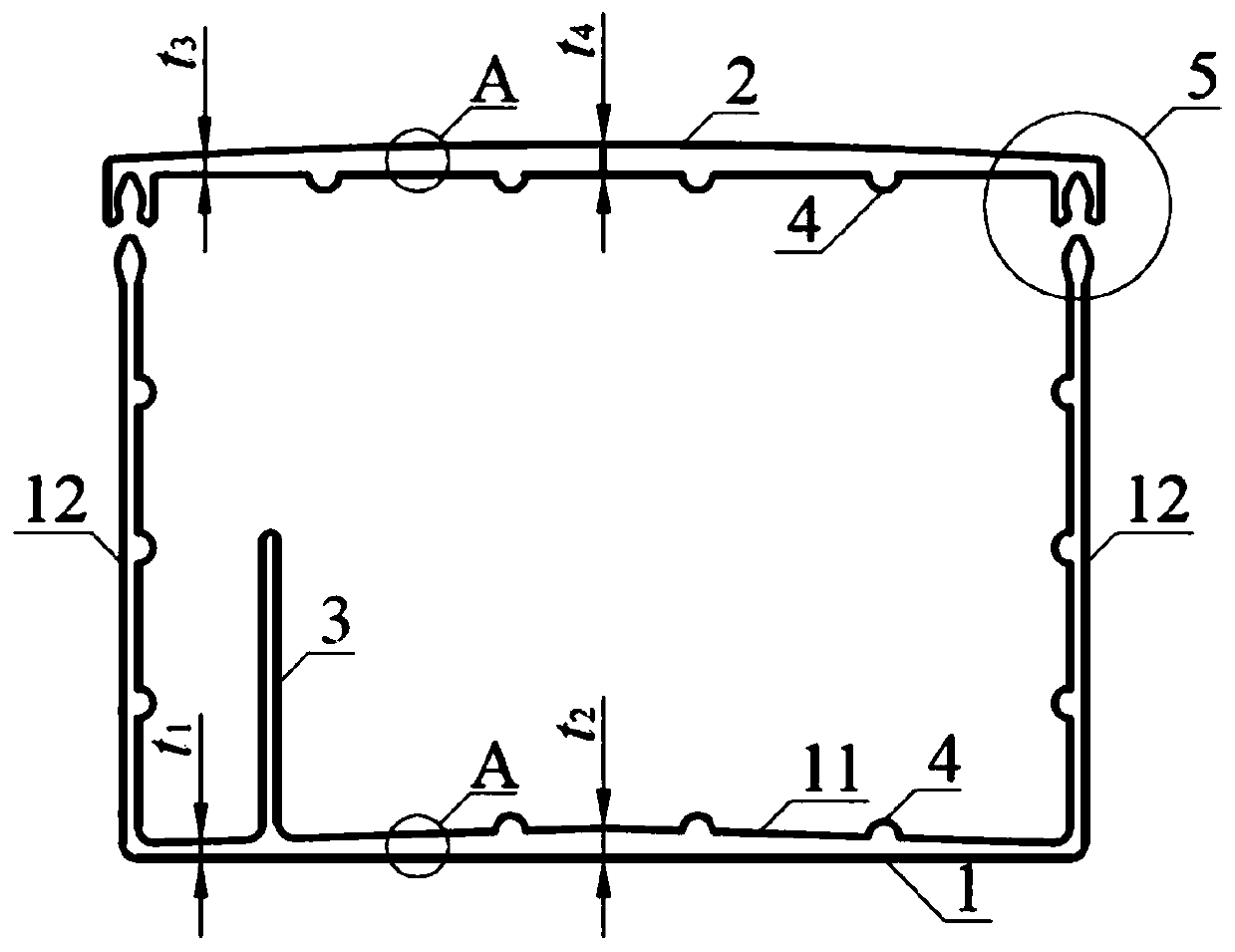
[0029] Such as figure 1 As shown, a fiber-reinforced composite cable trough includes a trough body 1 and a trough cover 2 . The tank body 1 is U-shaped and includes a bottom plate 11 and two side plates 12 . Along the transverse direction of the cable trough, the bottom plate 11 and the slot cover 2 are designed with a variable cross-section, and the top surfaces of the bottom plate 11 and the slot cover 2 are arc-shaped as a whole and protrude upward; specifically, the bottom plate 11 middle section thickness t 2 Greater than the section thickness t on both sides 1 , the middle section thickn...


PUM


Abstract

The invention belongs to the field of railway infrastructures, and relates to a fiber reinforced composite material cable trough, which comprises a trough body and a trough cover, wherein the trough body is U-shaped and comprises a bottom plate and two side plates; along the transverse direction of the cable trough, the bottom plate and the trough cover are both in variable cross-section design, and the thickness of the middle cross section of the bottom plate and the trough cover is larger than those of the cross sections of the two sides of the bottom plate and the trough cover respectively;the trough body is connected with the trough cover through a buckle; the inner surfaces of the bottom plate and the side plates and the outer surface of the trough cover are respectively provided with a plurality of stiffening projections along the length direction of the cable trough; and the trough body and the trough cover are both made of composite materials and provided with multiple layersof multidirectional reinforced fiber felts. The fiber reinforced composite material cable trough has the advantages of light weight, high longitudinal and transverse strength, high rigidity, high stability, high durability and the like, the trough cover is simple to mount and dismount, and the cable is convenient to maintain.

Description

technical field [0001] The invention belongs to the field of railway infrastructure, and in particular relates to a fiber-reinforced composite material cable trough. Background technique [0002] As the carrier of power and communication cables, the cable tray installed on the outside of the railway bridge not only bears the weight of itself and the cables, but also bears the live load and wind load of maintenance personnel occasionally walking on it. [0003] Most of the materials used in existing cable ducts are steel, and a few are composite materials. The structure of these cable troughs is basically similar. The top surface of the bottom plate of the trough body and the top surface of the trough cover are flat; and they are all made of thin plates of equal thickness, which are prone to warping and deformation due to low rigidity, especially on the side of the trough body. The upper end of the plate is a free end, which is more prone to inward or outward warping deforma...

Claims


Application Information

Patent Timeline
Patent Type & Authority Applications(China)
IPC IPC(8): H02G9/04
CPCH02G9/04
Inventor 曾志斌牛斌苏永华班新林马慧君尹京刘吉元
Owner RAILWAY ENG RES INST CHINA ACADEMY OF RAILWAY SCI
Why Eureka
Try Eureka