Fabricated composite structure bridge and construction method thereof
A combined structure and assembled technology, which is applied in the direction of erecting/assembling bridges, bridge construction, bridges, etc., can solve the problems of high cost and limited application scale of steel box girders
- Summary
- Abstract
- Description
- Claims
- Application Information
AI Technical Summary
Problems solved by technology
Method used
Image
Examples
Embodiment 1
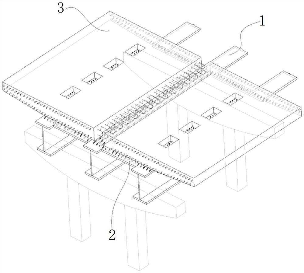
[0034] figure 1 Shown is the schematic diagram of the three-dimensional structure of the assembled composite structure bridge of the present invention, said bridge comprises I-beam longitudinal girder 1, rigid transverse connection system 2 and cantilever bridge deck 3, and the longitudinal middle part of cantilever bridge deck 3 is provided with butt joint hole, The top surface of the flange plate of the longitudinal beam 1 is preset with shear nails, and the shear nails pass through the butt joint holes of the cantilever bridge deck 3; the transverse connection system 2 supports the cantilever bridge deck 3 laterally; the longitudinal beam 1 supports the cantilever bridge deck 3 The longitudinal middle part and the inner longitudinal edge, and the outer longitudinal edge of the cantilever bridge deck 3 are free edges floating out;
[0035] The longitudinal beam 1 is placed on the T beam or the cover beam;
[0036]The butt holes of the cantilever bridge deck coincide with th...
Embodiment 2
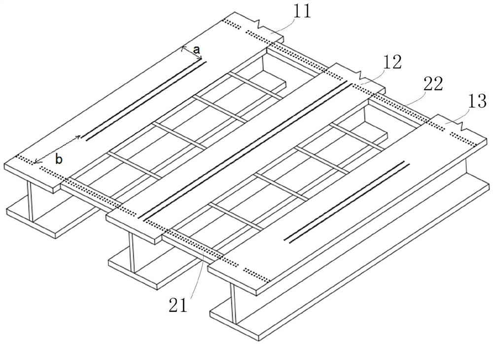
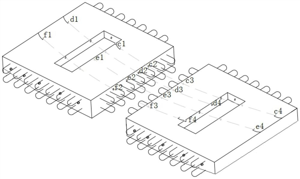
[0083] Such as Figure 6 Shown is another structural schematic diagram of two cantilever bridge decks arranged transversely, Figure 7 Shown is the structural diagram of the third longitudinal beam and beam, Figure 6 and Figure 7 Used in combination; the light-duty high-strength fabricated composite bridge includes I-beam longitudinal girders 11, 12, 13, rigid transverse linkages 21, 22 and cantilever bridge decks 31, 32, and the longitudinal middle part of the cantilever bridge deck is segmented with Butt joint holes for steel bars are reserved; shear stud areas are preset on the top surface of the flange plate of the outer longitudinal beam, and the shear stud areas correspond to and coincide with the butt joint holes one by one, while the shear stud areas The area passes through the butt joint hole of the cantilever deck; on both sides of the longitudinal centerline of the top surface of the flange plate of the inner longitudinal beam, there are preset continuous shear ...
Embodiment 3
[0088] Figure 8 Shown is the flow chart of the construction method of the prefabricated composite structure bridge of the present invention, described method comprises steps:
[0089] S101, I-steel longitudinal beams with shear studs preset on the top surface of prefabricated flange slabs, rigid transverse connections, and cantilever bridge decks with butt holes in the longitudinal middle;
[0090] The width of the butt joint hole is equal to the difference of the width of the flange plate at the top of the stringer minus 2a; the length of the butt joint hole is equal to the difference of the length of the cantilever bridge deck minus 2b;
[0091] Where a is the width of the supporting surface of the lapped or consolidated cantilever deck reserved for the top surface of the flange plate of the longitudinal girder, and the width a is reserved on both sides of the top of the longitudinal girder corresponding to the same cantilever deck;
[0092] b is the distance from the wide...
PUM
 Abstract
Description
Claims
Application Information
 - R&D
- Intellectual Property
- Life Sciences
- Materials
- Tech Scout
- Unparalleled Data Quality
- Higher Quality Content
- 60% Fewer Hallucinations
Browse by: Latest US Patents, China's latest patents, Technical Efficacy Thesaurus, Application Domain, Technology Topic, Popular Technical Reports.
© 2025 PatSnap. All rights reserved.Legal|Privacy policy|Modern Slavery Act Transparency Statement|Sitemap|About US| Contact US: help@patsnap.com


