Electric connector capable of pressing cable and assembly of electric connector

A technology of electrical connectors and connectors, which is applied to the parts, connections, and contact parts of connecting devices, can solve the problems of conductive belt fatigue deformation and other problems, and achieve the goal of eliminating poor contact, solving fatigue deformation, and preventing fatigue deformation Effect

Active Publication Date: 2015-04-15
CHINA AVIATION OPTICAL-ELECTRICAL TECH CO LTD
View PDF6 Cites 0 Cited by
  • Summary
  • Abstract
  • Description
  • Claims
  • Application Information

AI Technical Summary

Problems solved by technology

[0003] The purpose of the present invention is to provide an electrical connector capable of crimping cables, so as to solve the problem that the conductive strip is easily fatigued and deformed during the working process

Method used


Image

  • Electric connector capable of pressing cable and assembly of electric connector
  • Electric connector capable of pressing cable and assembly of electric connector
  • Electric connector capable of pressing cable and assembly of electric connector

Examples


Embodiment Construction

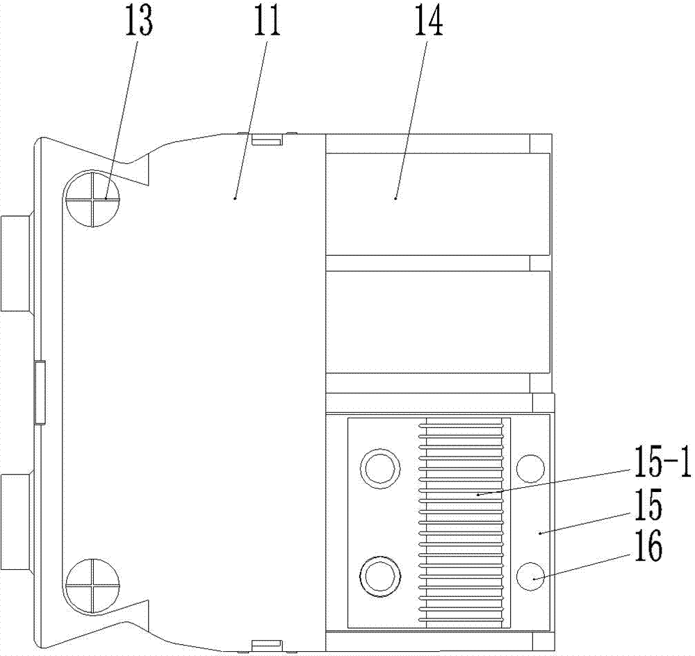
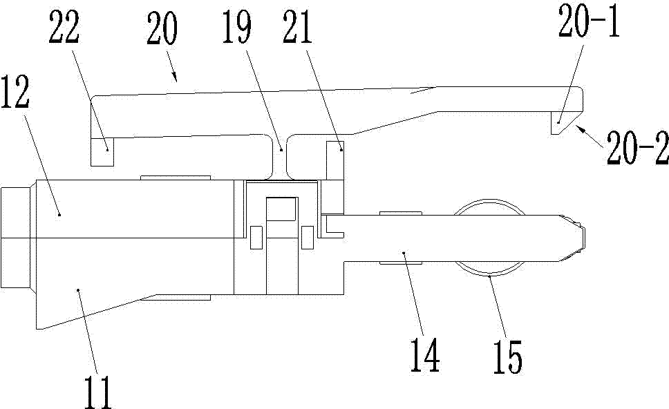
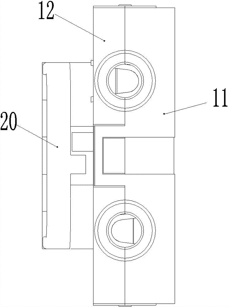
[0029] Embodiment 1 of the electric connector of the present invention that can be crimped cables, such as Figure 1-5As shown, the electrical connector uses the front end as the plug-in end, and includes an insulating shell, which is formed by fastening the cover plate 11 and the base 12 up and down. The lock between the two is fastened, and the structure and working principle of the lock are prior art, and will not be repeated here. The cover plate and the base are further fixed by screws 13 after the lock is initially locked, and the cover plate 11 and the base 12 is respectively provided with the tongue 14 that extends forward at the front end, and the tongue on the cover plate 11 and the base 12 is respectively fixed with conductive sheet 15, and two conductive sheets are arranged on the left and the right, and the front end of conductive sheet 15 is , that is, a conductive strip 15-1 is provided on the part on the corresponding plug tongue, and the conductive strip 15-1 ...


PUM


Abstract

The invention relates to an electric connector capable of pressing a cable. The electric connector comprises a shell and electric conduction plates, wherein the electric conduction plates are provided with electric conduction bands, the electric conduction bands are provided with contact parts which are bent and raised, the front end of the shell is provided with inserting tongues, the electric conduction plates are fixedly arranged on the corresponding inserting tongues, the inserting tongues are provided with limit blocks, the direction of the limit blocks on the inserting tongues is consistent with the raised direction of the electric conduction bands on the inserting tongues, and the distance between one sides of the limit blocks deviated from the corresponding inserting tongues and the inserting tongues is less than that between the top parts of the contact parts and the corresponding inserting tongues; and the shell is formed by fastening a base and a cover plate up and down, the electric conduction plates are pressed and fixed between the base and the cover plate of the shell, the rear ends of the electric conduction plates are provided with a line pressing sleeve, the line pressing sleeve is covered between the base and the cover plate of the shell, the compression amount of the electric conduction bands can be limited through the limit blocks, thus the compression amount of the electric conduction bands can be preset on the premise that the limit blocks are in reliable contact with a contact piece of an adaptive connector, the problem of fatigue deformation of the electric conduction bands is prevented from happening, and the problem that the electric conduction bands are easy in fatigue deformation during a work process is solved.

Description

technical field [0001] The invention relates to the field of electrical connectors, in particular to an electrical connector capable of crimping cables and components thereof. Background technique [0002] Conductive strip is a common contact in electrical connectors. For example, Chinese patents with patent numbers 022253334.2, 2007201483866, 2005200010512, 2006200029547 and 2008201380525 all record related technologies. As the name suggests, the conductive strip is strip-shaped, and its two There is a protruding contact part between the ends, the contact part is used to make electrical contact with the corresponding contact piece of the matching connector when the corresponding electrical connector is working, and the contact part is elastic during the contact with the matching connector Deformation, so as to tighten the contact with it in electrical contact, to ensure the reliability of the contact; among the current electrical connectors, the conductive strip is used as ...

Claims


Application Information

Patent Timeline
Patent Type & Authority Patents(China)
IPC IPC(8): H01R13/02H01R13/05H01R13/502H01R13/40H01R13/639H01R24/00
Inventor 张星
Owner CHINA AVIATION OPTICAL-ELECTRICAL TECH CO LTD
Why Eureka
Try Eureka