Injector for a flexible ophthalmologic implant

A technology for injectors, implants, applied in the field of injectors, which can solve the problem of parts not completely satisfactory

Inactive Publication Date: 2012-10-03
萨迪克・穆哈贝丁
View PDF0 Cites 1 Cited by
  • Summary
  • Abstract
  • Description
  • Claims
  • Application Information

AI Technical Summary

Problems solved by technology

[0007] The part is not entirely

Method used


Image

  • Injector for a flexible ophthalmologic implant
  • Injector for a flexible ophthalmologic implant
  • Injector for a flexible ophthalmologic implant

Examples


Embodiment Construction

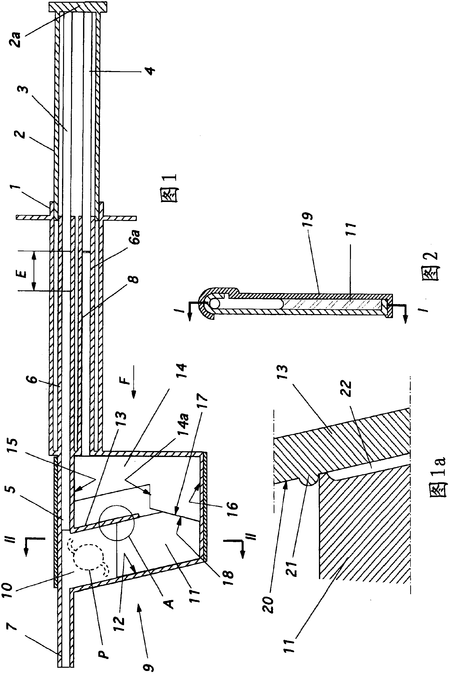
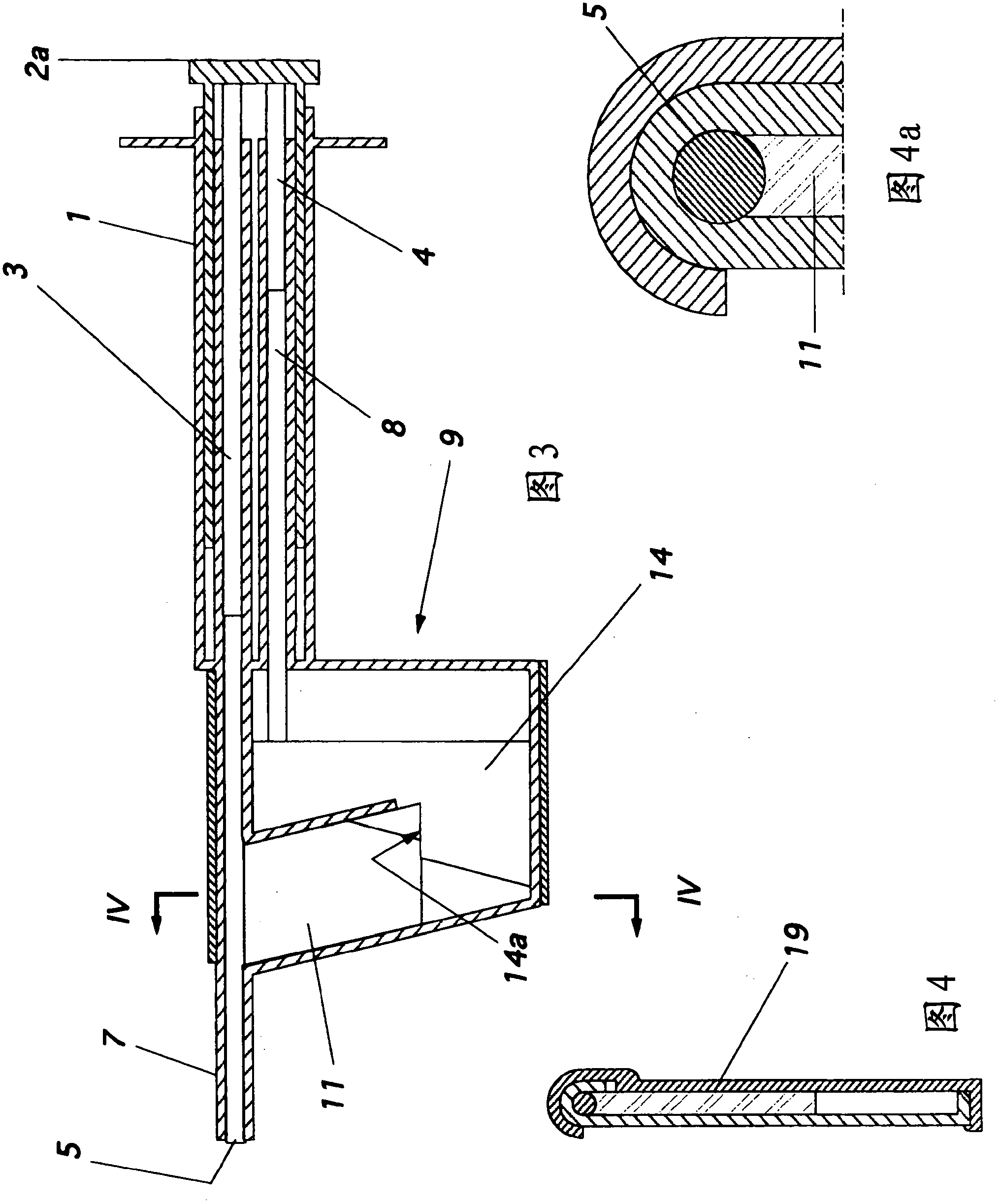
[0024] Referring to the drawings, it can be seen that the injector has a body 1 guiding a tubular member 2 , the total pusher, enclosing two parallel rods 3 and 4 .

[0025] Through its movement, the rod 3 can act on the expulsion pusher 5 , which is guided in the tube 6 of the body 1 and forms an extension of the usual hollow needle 7 .

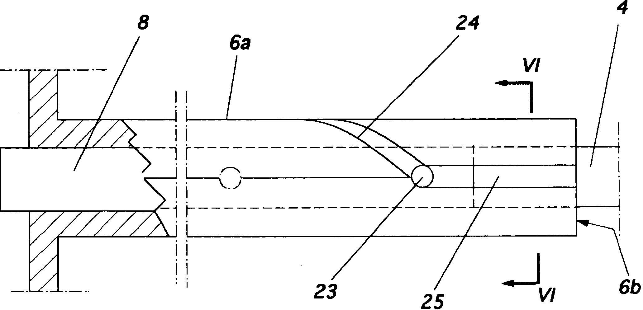
[0026] The rod 4 guided in the tube 6a can, through its movement, act on a bending pusher 8 which opens into the box 9 of the main body.

[0027] The cassette 9 has a compartment 10 in which the implant P is placed, which opens laterally into the needle 7 .

[0028] The bending of the implant is achieved by movement of the bending member 11 , which is guided between the parallel walls 12 and 13 of the box.

[0029] The movement of the bending member 11 is ensured by a cam 14 which is guided between the parallel walls 15 and 16 of the box.

[0030] The cam 14 has an inclined part 17 which is in contact with a second inclined part 18 of the ...


PUM


Abstract

The invention relates to an injector characterised in that said injector comprises a general tappet (2) having two rods (3, 4), one of which can engage with an ejection tappet (5) while the other can engage, via the middle section of a folding tappet (8), with a mechanism enabling the implant (P) to be folded and inserted in a hollow needle (7), a means being provided for inhibiting, when desirable, the action of either one of the rods of the tappet.

Description

technical field [0001] The present invention relates to injectors for bendable ophthalmic implants. Background technique [0002] In cataract treatment, the lens is removed and replaced with a lens implanted in the lens capsule. The lens is made of an elastically deformable flexible material that can be bent and compressed. [0003] In the prior art, the implants are in the form of biconvex lenses with a diameter of 3 to 7 mm, which have haptics at their periphery, usually in the form of curved arms, with the function of keeping the lens inside the lens capsule Centrally, the whole has an overall diameter of about 10 to 15 mm. [0004] The implant is bent and introduced into a hollow needle having a pusher that allows expulsion of the implant as the needle is inserted into the lens capsule. [0005] Injectors are known in which the hollow needle has a side opening leading into a chamber in which the implant is placed, said chamber having a pivoting blade opposite the side...

Claims


Application Information

Patent Timeline
IPC IPC(8): A61F2/16
CPCA61F2/1672
Inventor 萨迪克・穆哈贝丁
Owner 萨迪克・穆哈贝丁
Why Eureka
Try Eureka