Automatically controlled ventilation system

A controller and minute ventilation technology, applied in the ventilator field, can solve the problems that cannot be automatically determined and provided

Active Publication Date: 2012-10-03
KONINKLIJKE PHILIPS ELECTRONICS NV
View PDF15 Cites 28 Cited by
  • Summary
  • Abstract
  • Description
  • Claims
  • Application Information

AI Technical Summary

Problems solved by technology

As such, current devices cannot automatically determine and provide the optimal target tidal volume and pressure support delivered to the patient based on changing respiratory or other physiological characteristics

Method used


Image

  • Automatically controlled ventilation system
  • Automatically controlled ventilation system
  • Automatically controlled ventilation system

Examples


Embodiment Construction

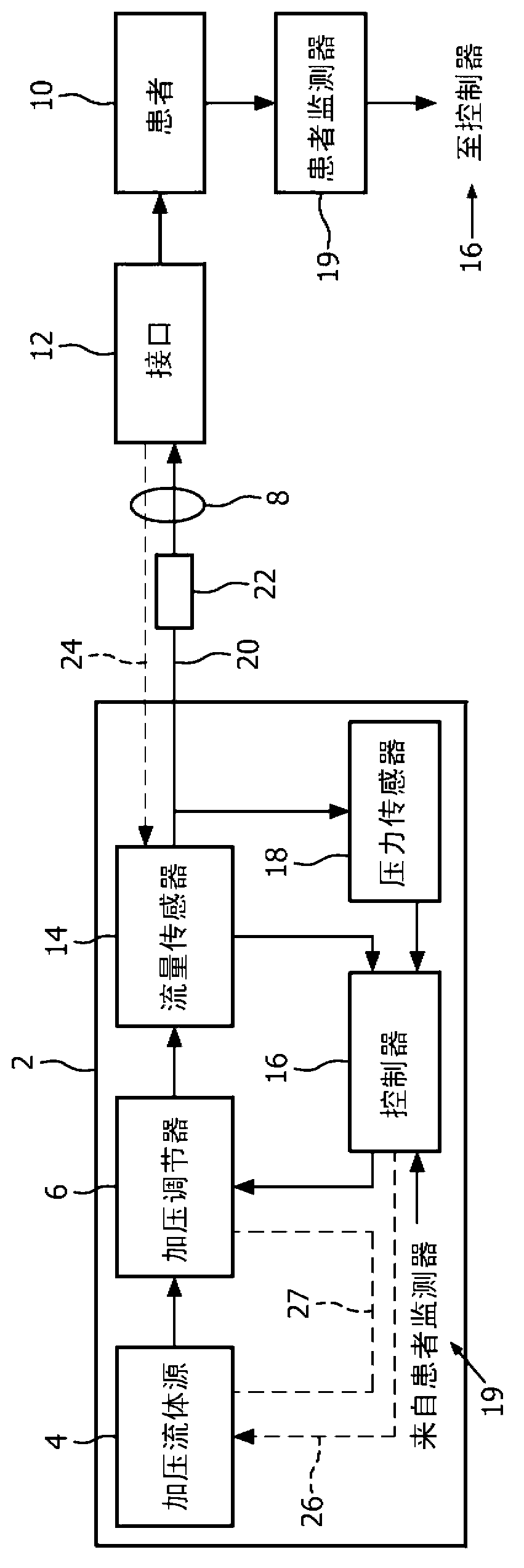
[0044] figure 1 An exemplary embodiment of a pressure support system or ventilator 2 according to the principles of the invention is illustrated. The term "ventilator" as used herein refers to any device that delivers a flow of breathing gas to a patient at variable pressures and is not intended to be limited to life support ventilation systems only.

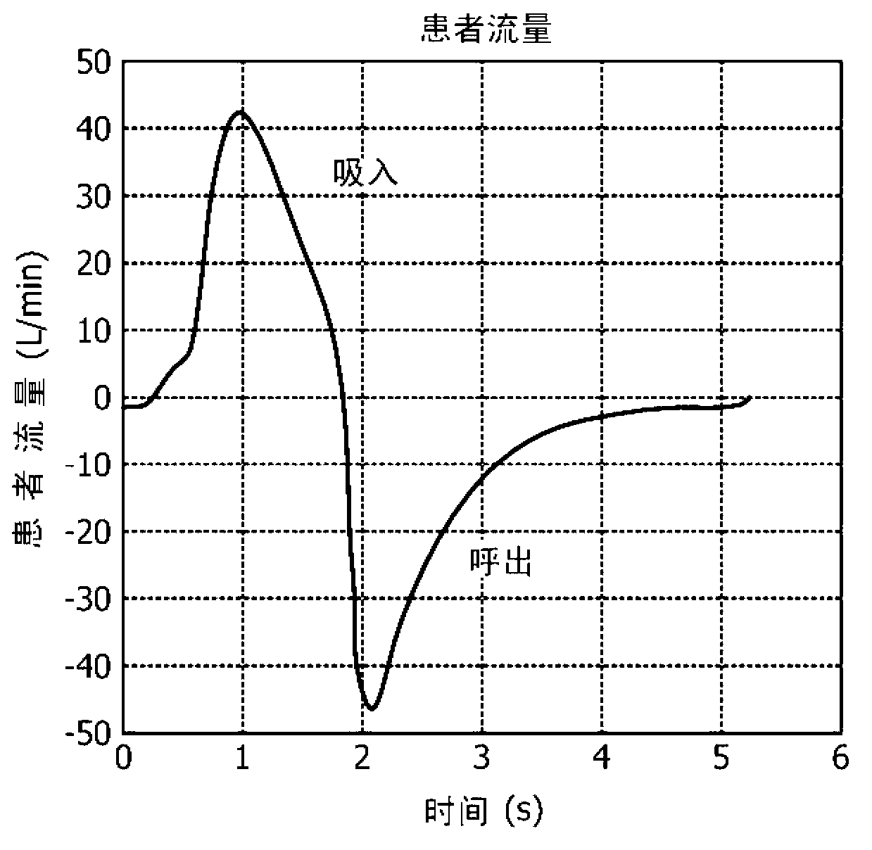
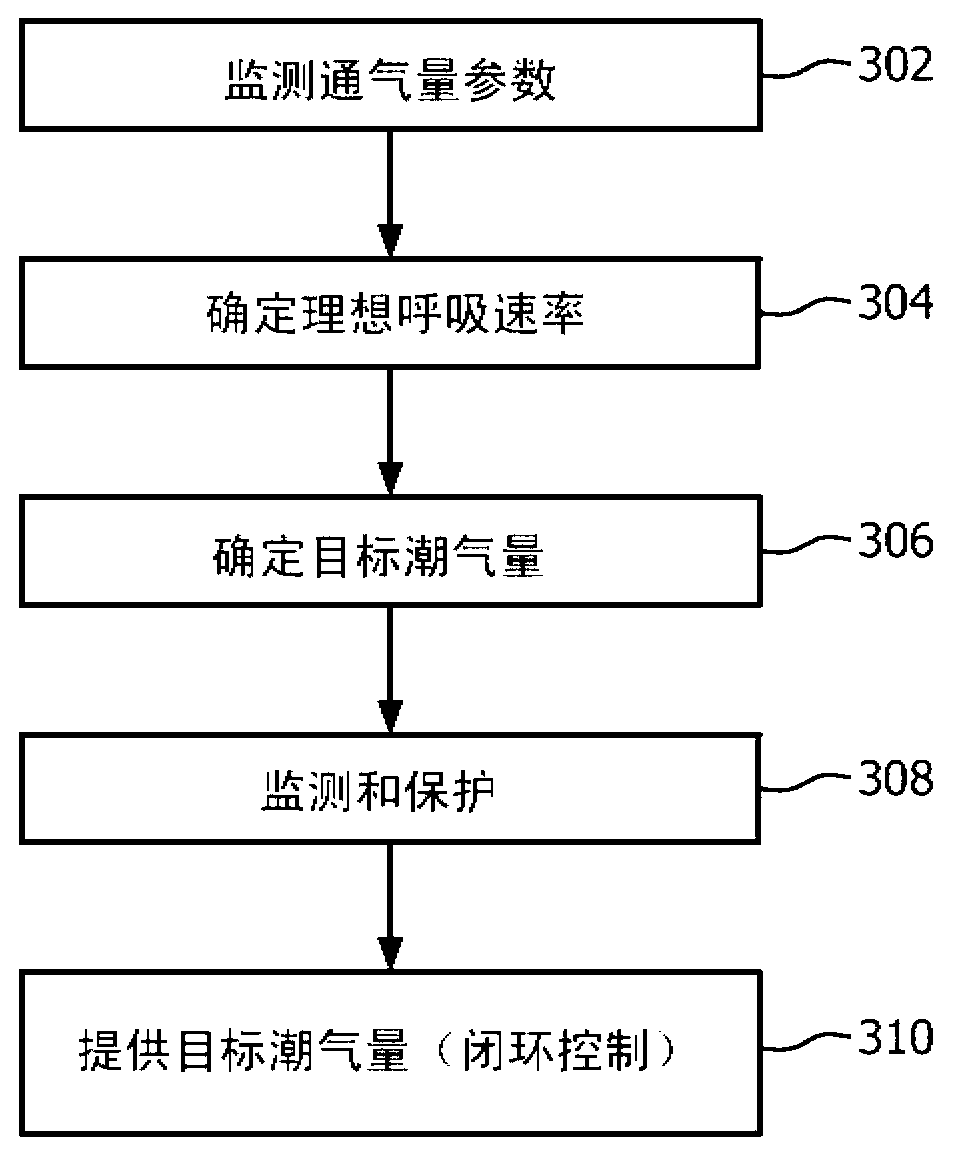
[0045] System 2 measures at least one characteristic of the patient's respiratory airflow; calculates or determines a time-based target parameter, such as a desired respiratory rate, based on the at least one measured characteristic; and calculates a breath amplitude-based parameter, such as a target tidal volume, delivered to the patient. the target parameter; and then delivering the calculated breath amplitude-based target parameter to the patient. figure 2 The relationship between flow and tidal volume is shown in . Such as figure 2 As shown, positive flow indicates the flow into the patient during inspiration. Negative...


PUM


Abstract

A system for controlling and regulating breathing gas supplied to a patient that includes a pressure generator system that provides breathing gas to a patient and a patent circuit that delivers the breathing gas to the patient. The system includes an interface device coupled to the patient circuit to communicate the flow of gas to the patient' airway. A sensor detects a parameter indicative of a flow of breathing gas delivered to the patient. A controller coupled to the sensor and the pressure generator system measures at least one characteristic of respiratory airflow of a patient and calculates a target breath-amplitude -based parameter and a time -based parameter of at least a portion of the patient's respiratory cycle to be delivered to the patient based on the at least one characteristic of respiratory airflow.

Description

[0001] This patent application claims the benefit of priority under 35 U.S.C. §119(e) to U.S. Provisional Application No. 61 / 297400, filed January 22, 2010, the contents of which are hereby incorporated by reference. technical field [0002] The present invention relates to a ventilator and a method of controlling the ventilator to provide a desired target volume of fluid, such as air or an oxygen mixture, to a patient. Background technique [0003] Conventional ventilators can be used to deliver a fluid, such as air or an oxygen mixture, to a patient in a set target volume ventilation mode, in which the ventilator attempts to deliver a preset volume of fluid to the patient during inspiration. To adjust the volume of fluid delivered to the patient during inhalation to achieve this target volume during each inhalation, the ventilator adjusts the pressure of the fluid provided to the patient. For example, for a given inspiratory phase over multiple breathing cycles, increasing...

Claims


Application Information

Patent Timeline
Patent Type & Authority Applications(China)
IPC IPC(8): A61M16/00
CPCA61M16/12A61M16/0051A61M16/0066A61M2205/15A61M2230/42A61M2016/0027A61M2016/0039A61M16/06A61M2016/003A61M16/04A61M2230/60A61M2205/50A61M2210/1014A61M16/0069A61M16/024
Inventor M·T·凯恩B·I·谢利
Owner KONINKLIJKE PHILIPS ELECTRONICS NV
Why Eureka
Try Eureka