Transmitter, transmission method, receiver, reception method, program, and integrated circuit
A technology of a transmitting device and a receiving device, applied in the fields of transmitting device, transmitting and receiving device, receiving, program and integrated circuit, can solve the problem of increasing the calculation amount of the receiving device, increasing the dynamic range of the receiving device, increasing the number of signal processing bits, etc. question
- Summary
- Abstract
- Description
- Claims
- Application Information
AI Technical Summary
Problems solved by technology
Method used
Image

Examples
Embodiment approach 1
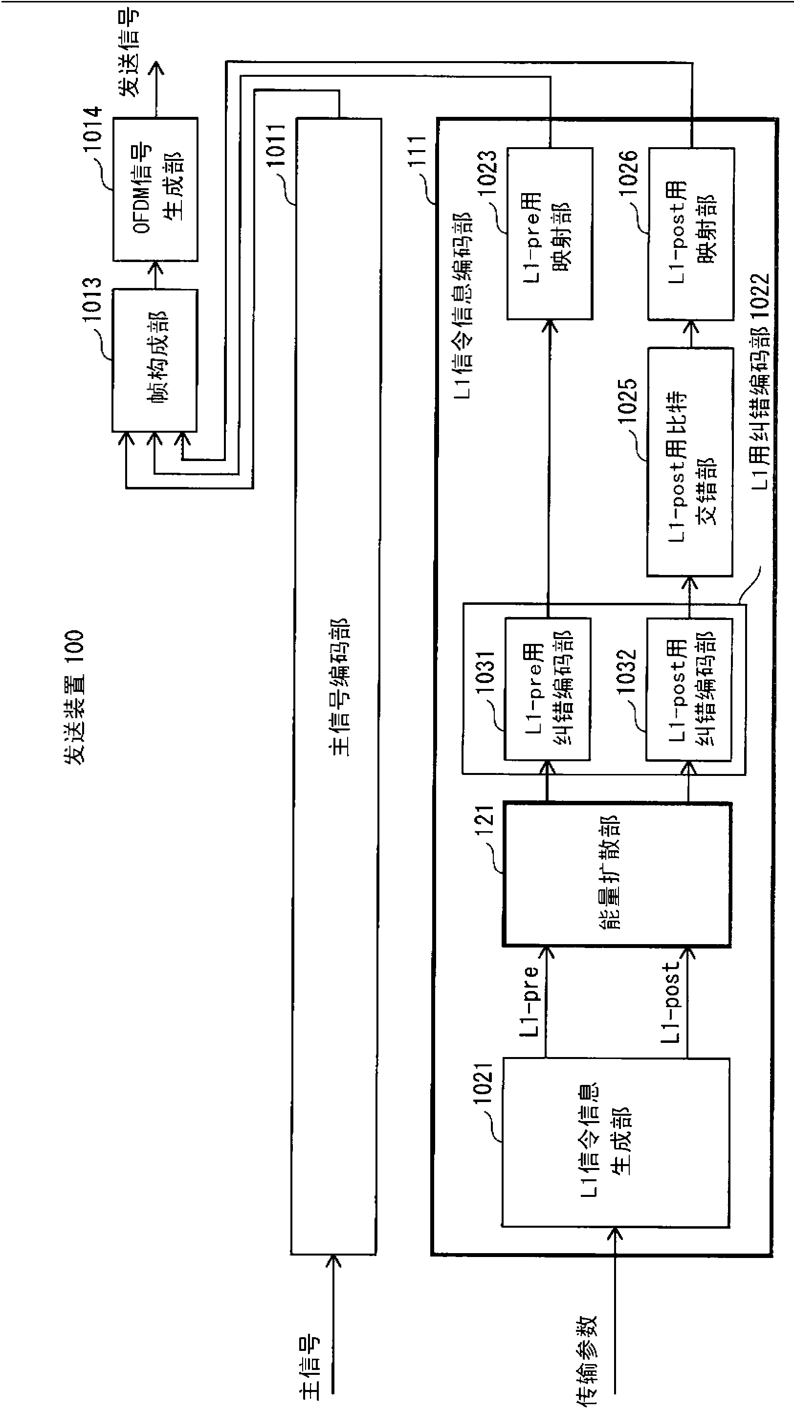
[0146] figure 1 It is a diagram showing the configuration of the transmission device 100 in Embodiment 1 of the present invention. The same reference numerals are used for the same constituent elements as those of the conventional transmission device, and description thereof will be omitted.
[0147] figure 1 The sending device 100 with Figure 32 Compared with the conventional transmission device 1000 shown, the energy dispersal unit 121 is added to the L1 signaling information encoding unit 111 .
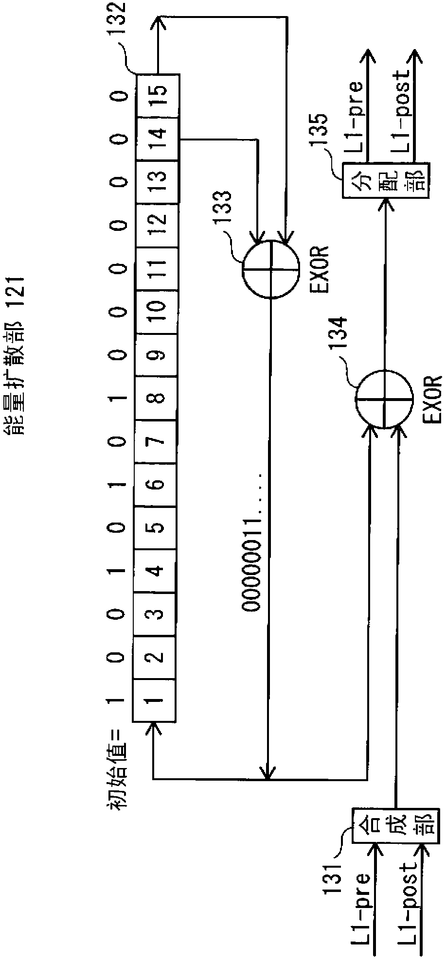
[0148] exist figure 1 In the transmitting device 100, the energy dispersal unit 121 sequentially performs energy dispersal on the L1-pre information and the L1-post information generated by the L1 signaling information generation unit 1021. The L1-pre error correction coding unit 1031 performs error correction coding of the energy-diffused L1-pre information by BCH coding and LDPC coding. The L1-post error correction coding unit 1032 performs error correction coding of the...
Embodiment approach 2
[0163] Figure 4 It is a figure showing the structure of the transmission apparatus 200 in Embodiment 2 of this invention. The same reference numerals are used for the same constituent elements as those of the conventional transmission device and the transmission device of Embodiment 1, and description thereof will be omitted.
[0164] Figure 4 The sending device 200 and Figure 32 Compared with the conventional transmission device 1000 shown, the energy dispersal unit 121 is added to the L1 signaling information encoding unit 211 . However, in Embodiment 1 and Embodiment 2, the additional position of the energy diffusion part 121 differs.
[0165] exist Figure 4 In the transmission device 200 of , the energy dispersal unit 121 compares the error-corrected encoded L1-pre information output from the L1-pre error-corrected encoding unit 1031 and the error-corrected encoded information output from the L1-post error-corrected encoded unit 1032 L1-post information, energy di...
Embodiment approach 3
[0178] Figure 6 It is a figure showing the structure of the transmission apparatus 300 in Embodiment 3 of this invention. The same reference numerals are used for the same constituent elements as those of the conventional transmission device, and description thereof will be omitted.
[0179] Figure 6 The sending device 300 and Figure 32 Compared with the conventional transmission device 1000 shown, the L1 signaling information generation unit 321 in the L1 signaling information encoding unit 311 is replaced.
[0180] exist Figure 6 In the transmitting device 300 of , the L1 signaling information generator 321 generates L1 signaling information according to the transmission parameters, that is, converts the transmission parameters into L1 signaling information (L1-pre information and L1-post information) and outputs it. In this case, the L1 signaling information generation unit 321 inverts the bit pattern of the L1-post information part (excluding the PLP_ID) related to...
PUM
 Abstract
Description
Claims
Application Information
 - R&D
- Intellectual Property
- Life Sciences
- Materials
- Tech Scout
- Unparalleled Data Quality
- Higher Quality Content
- 60% Fewer Hallucinations
Browse by: Latest US Patents, China's latest patents, Technical Efficacy Thesaurus, Application Domain, Technology Topic, Popular Technical Reports.
© 2025 PatSnap. All rights reserved.Legal|Privacy policy|Modern Slavery Act Transparency Statement|Sitemap|About US| Contact US: help@patsnap.com