
Hand-operated adjusting arm capable of completely locking adjusting shaft and worm
A technology of manual adjustment and shaft adjustment, applied in the field of manual adjustment arm, to achieve the effect of reliable positioning, long service life and convenient operation
- Summary
- Abstract
- Description
- Claims
- Application Information
AI Technical Summary
Problems solved by technology
Method used
Image

Examples
Embodiment Construction
[0030] Specific embodiments of the present invention will be described below with reference to the accompanying drawings.
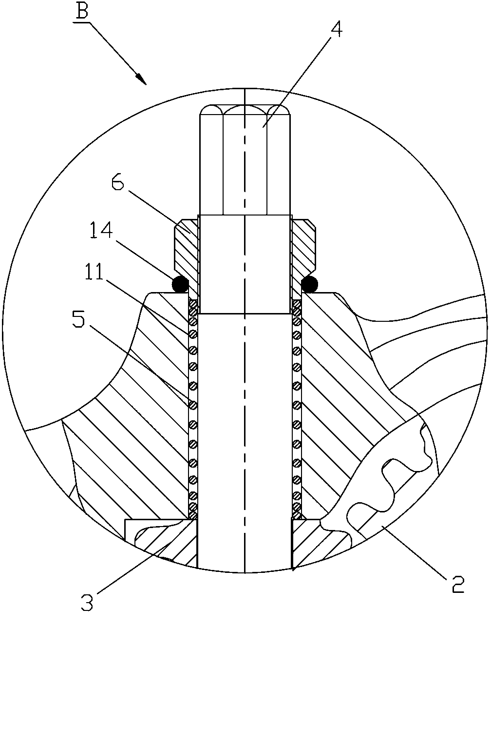
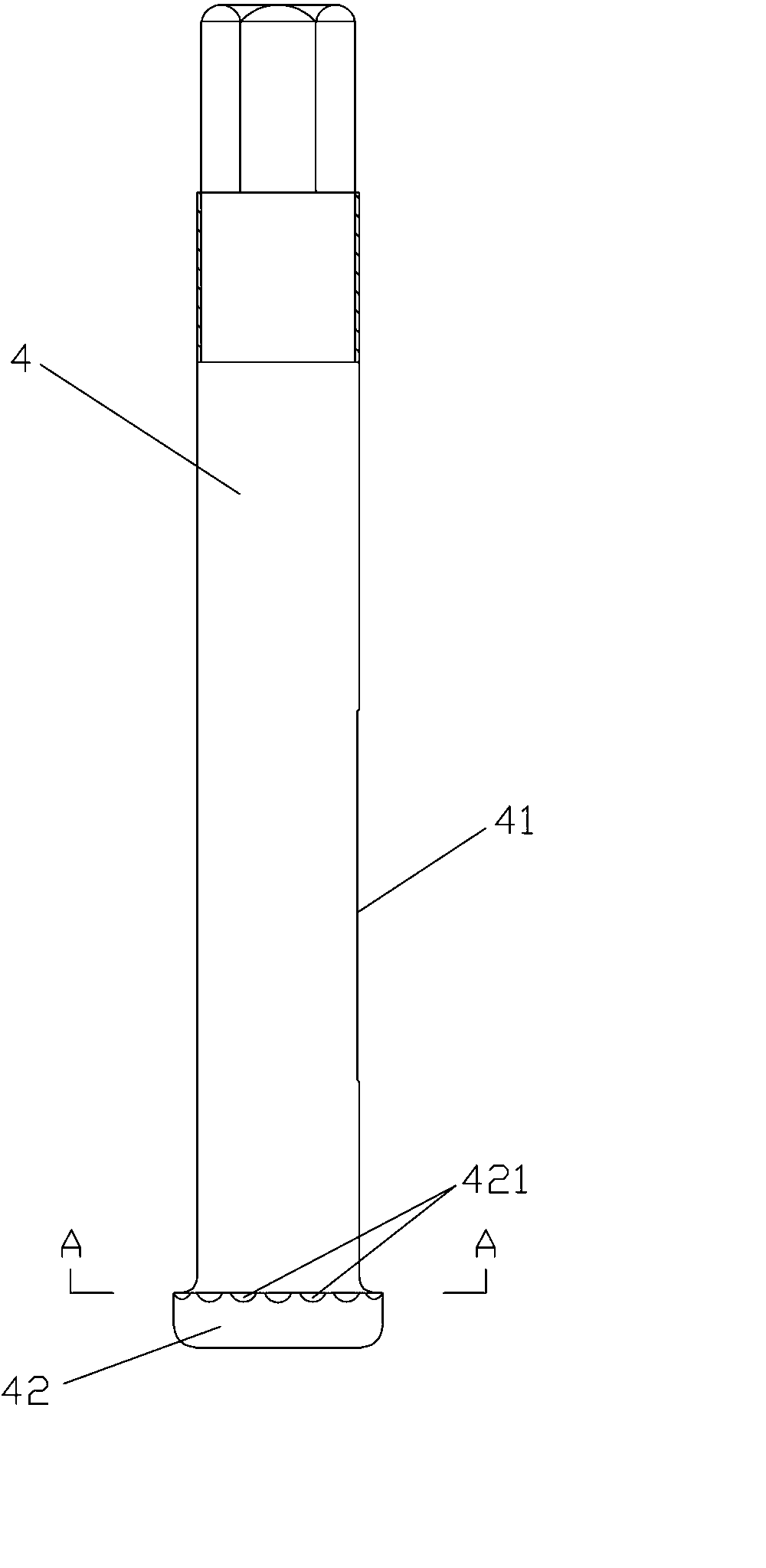
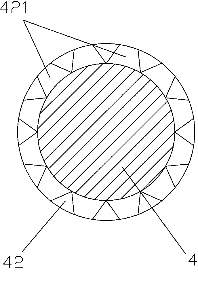
[0031] A manual adjusting arm with complete locking of the adjusting shaft and worm, see figure 1 or figure 2 , mainly consists of a housing 1, a worm wheel 2 installed in the housing 1, a worm 3 meshing with the worm gear 2, an adjustment shaft 4 passing through the worm 3 and the housing 1, a large spring 5, and a threaded cap 6 that compresses the large spring 5 And positioning small steel ball 7 is formed. refer to figure 1 and combine image 3 The housing 1 is correspondingly provided with a mounting hole 11 that communicates with the inner hole 30 of the worm, and the lower port of the mounting hole 11 forms an enlarged part 12, and two symmetrical small steel balls 7 are inserted into the part where the upper end surface of the enlarged part 12 is connected with the side wall, There is a central blind hole 40 in the middle of the lower end sur...
PUM
 Abstract
Description
Claims
Application Information