
High frequency domain energy concentration synchronization method based on fractional Fourier transform

A fractional Fourier, energy-concentrated technology, applied in multi-frequency code systems and other directions, can solve problems such as overall communication signal spectrum broadening

Inactive Publication Date: 2012-10-10
HARBIN ENG UNIV
View PDF7 Cites 11 Cited by
  • Summary
  • Abstract
  • Description
  • Claims
  • Application Information

AI Technical Summary

Problems solved by technology

[0005] The purpose of the present invention is to provide a synchronous signal with continuous time-domain waveform and smooth frequency change, which can solve the problem of broadening the spectrum of the overall communication signal due to frequency hopping of the synchronous signal under the premise of ensuring time-frequency synchronization performance and reducing system complexity A Fractional Fourier Transform-Based High Frequency Domain Energy Concentration Synchronization Method for the Problem of

Method used


Image

  • High frequency domain energy concentration synchronization method based on fractional Fourier transform
  • High frequency domain energy concentration synchronization method based on fractional Fourier transform
  • High frequency domain energy concentration synchronization method based on fractional Fourier transform

Examples


Embodiment Construction

[0041] The following examples describe the present invention in more detail:

[0042] figure 1 It is a schematic diagram of the synchronous signal structure of the present invention. where f 0 Is the carrier frequency, and k is the modulation frequency of the chip signal. It can be seen that the synchronous signal is composed of three chip signals, the length of the first chip signal is equal to the length of the third chip signal, and their frequency change rates are the same, the length of the second chip signal is the first 2 times the length of the segment cut signal, and their frequency change rates are opposite.

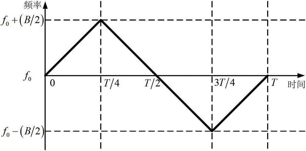
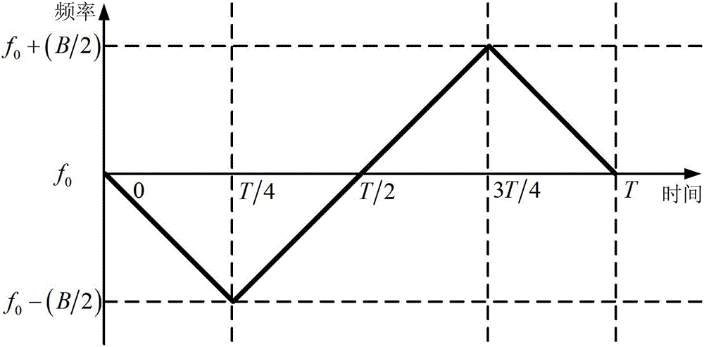
[0043] The synchronous signal of the present invention has two optional frequency change forms, figure 2 It is a schematic diagram of the first frequency change of the synchronization signal in the present invention. where f 0 is the carrier frequency, B is the FM bandwidth of the synchronization signal, and T is the time length of the synchronization si...


PUM


Abstract

The invention provides a high frequency domain energy concentration synchronization method based on fractional Fourier transform. Three chirp signals are connected in series as a synchronization signal, and the synchronization signal is transmitted at a transmitting terminal; the transmitted synchronization signal is received at a receiving terminal, and the fractional Fourier transform in performed on the received synchronization signal to produce a fractional domain magnitude spectrum; three peak value positions of the fractional domain magnitude spectrum are detected, and the three peak value positions are compared with peak value positions in the case of without time offset and without frequency offset to produce an offset deviation; calculating time offset and frequency offset of the system according to the offset deviation; and adjusting a time window position of the system and the frequency of local carrier waves according to the time offset and the frequency offset of the system to realize synchronization. Aiming at low synchronization signal frequency domain energy concentration and susceptible system synchronization accuracy problems in synchronization methods adopted in modern frequency modulation communication systems, a synchronization method based on the fractional Fourier transform is provided. The method is applicable for synchronization of communication signals.

Description

technical field [0001] The invention relates to a time-frequency joint synchronization method with high frequency domain concentration. Background technique [0002] As a key technology in the communication system, synchronization technology directly affects the performance of the communication system. The early synchronization method is the time-domain synchronization method, which utilizes the autocorrelation of the synchronization signal, uses the correlation operation to process it at the receiving end, and realizes synchronization by searching for the correlation peak. Since frequency offset often exists in modern wireless communication systems, time-frequency joint synchronization methods are often used. [0003] In order to solve the problems of poor time-frequency synchronization performance and high system complexity of modern time-frequency synchronization methods, in 2009, Sha Xuejun and others proposed a time-frequency joint synchronization method based on fract...

Claims


Application Information

Patent Timeline
Patent Type & Authority Applications(China)
IPC IPC(8): H04L27/26
Inventor 郭黎利周彬孙志国杨鹏
Owner HARBIN ENG UNIV
Learn More