Artificial diamond blister tray molding equipment

A technology of molding equipment and blister trays, which is applied in the field of blister molding equipment for rhinestone blister trays, can solve the problems of low molding efficiency, inconvenient operation, and unstable movements, etc., and achieves simple and reasonable structure, convenient operation, The effect of improving the efficiency of blister molding

Active Publication Date: 2012-10-17
虞雅仙
5 Cites 21 Cited by

AI-Extracted Technical Summary

Problems solved by technology

[0003] But, in the above-mentioned patent document, the tooling tray is placed on the base, the tooling tray is taken and placed between the suction template and the base, the blister material is put into and the rhinestone blister tray is taken out from between the suction template and the pressure frame plate, so In order to ensure the operating space, it is required to have a large o...

Method used

1) as shown in Figure 2, empty frock plate 6 upwards jacks up, changes frock plate between press frame plate 5 and suction template 9, puts into frock plate 6 that arranges rhinestones; can drop simultaneously Suction template 9 is convenient to operate to increase open space; As shown in Figure 3, suction template 9 rises, and plastic-absorbing material 16 is put in...

Abstract

The invention discloses artificial diamond blister tray molding equipment comprising a frame, a vacuum pump, a heating device, a pedestal, a suction template, a frame pressing plate, and a tooling plate. A gap is kept between the side circumference of the tooling plate and the suction template or an annular ring, wherein the gap communicates with the vacuum pipe through an air pipe. The air pipe is vertically slidably connected with the pedestal, and is sealed with the pedestal. Under the driving of an air pipe cylinder arranged on the frame, the air pipe moves up and down. The tooling plate is arranged on the top of the air pipe. With the technical scheme provided by the invention, the jacking top of the air pipe can enter an opened space between the suction template and the frame pressing plate. Therefore, tooling plate fetching, blister material feeding and artificial diamond blister tray fetching can be operated in a same opened space, and feasibility for configuring only one elevation height for the suction template is provided. Therefore, the structure is greatly simplified, and the operation is convenient.

Technology Topic

EngineeringBlisters +2

Image

  • Artificial diamond blister tray molding equipment
  • Artificial diamond blister tray molding equipment
  • Artificial diamond blister tray molding equipment

Examples

  • Experimental program(1)

Example Embodiment

[0019] Example 1:
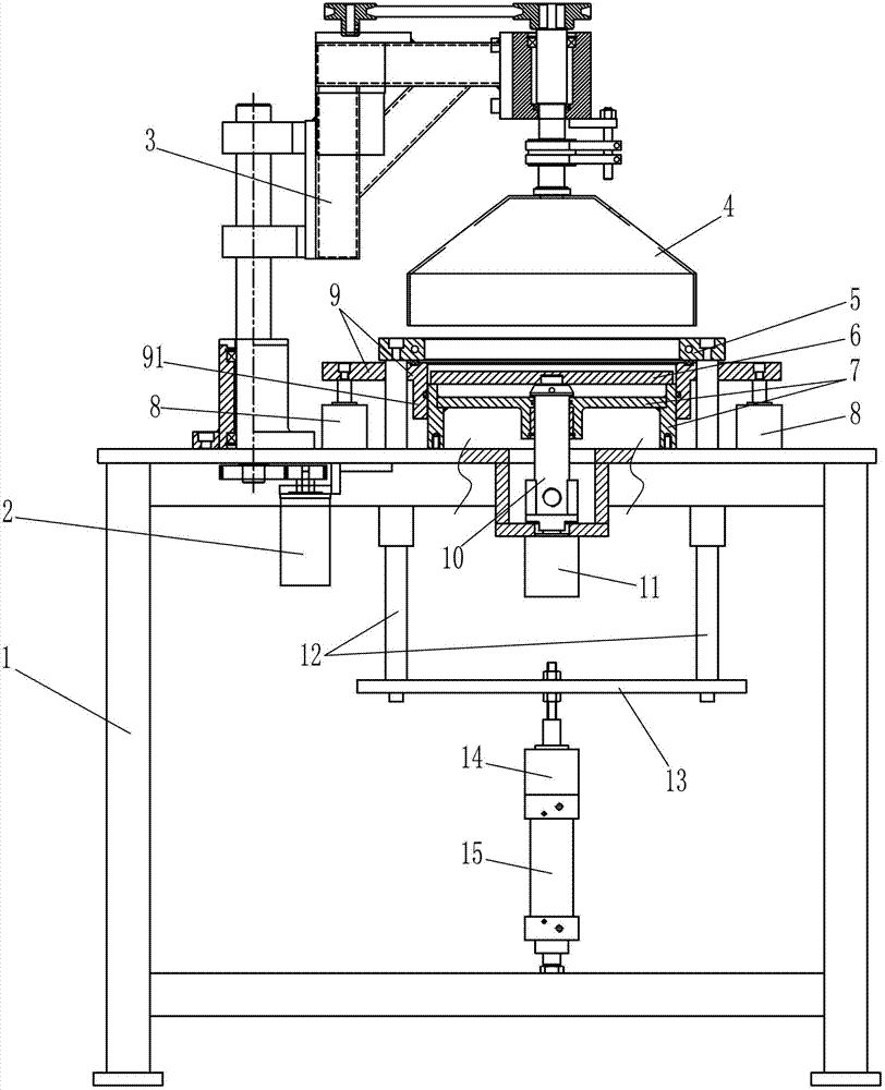
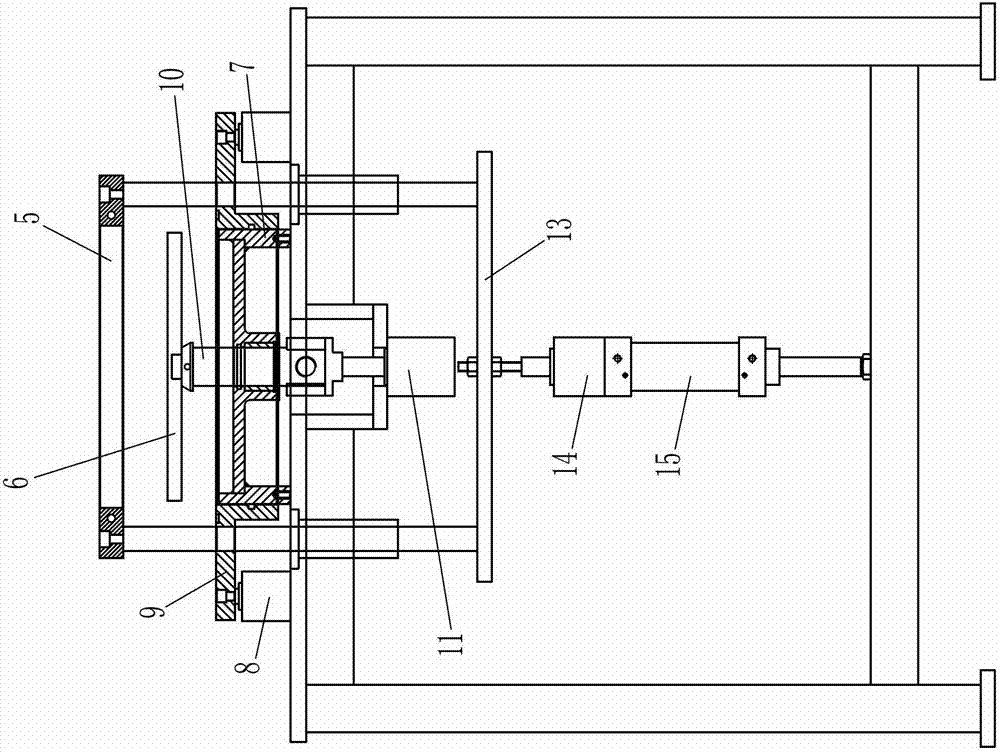
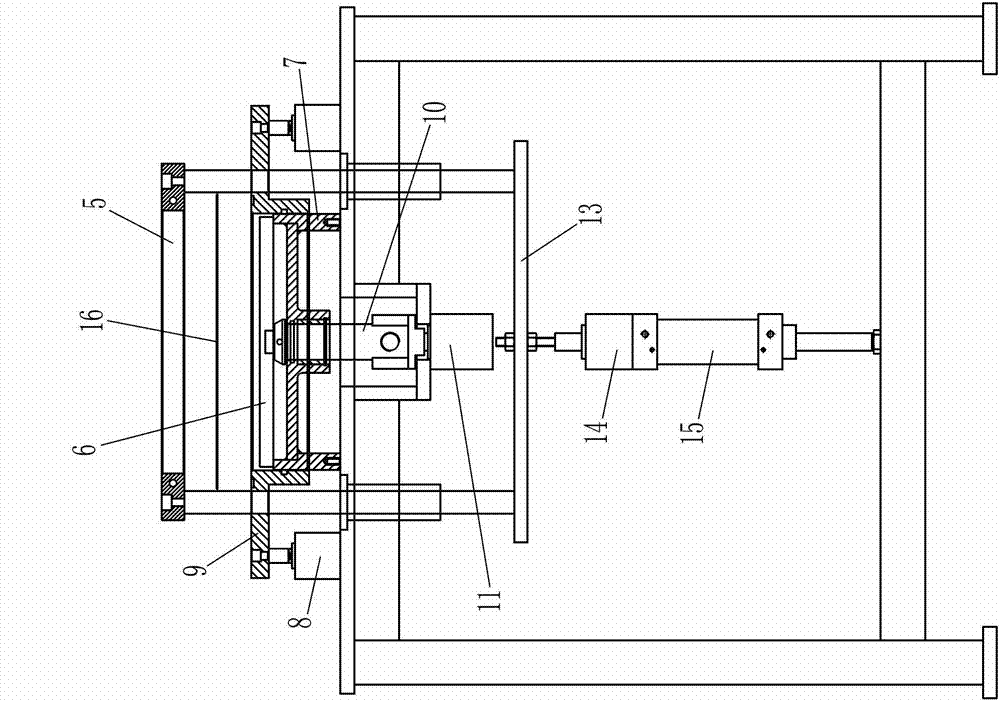
[0020] Such as figure 1 The molding equipment of a rhinestone blister tray shown includes a frame 1, a vacuum pump (not shown in the figure) and a heater 4. The frame 1 is fixedly provided with a base 7, and the base 7 is provided with a suction template 9. The suction template 9 is provided with a compression frame plate 5 that clamps the blister material 16 together with the suction template 9. A tooling plate 6 is placed in the center of the suction template 9, and a number of embedded holes for embedded rhinestones are arranged on the tooling plate 6. The bottom of the hole is provided with a vent hole, which communicates with the vacuum pump via a vent pipe 10, the heater 4 can be erected above the compression frame plate 5 by a moving mechanism; the side circumference of the tooling plate 6 is connected to the suction template 9 or an annular ring There is a gap between 91, and the gap is communicated with the vacuum pump through the vent pipe 10; the compression frame plate 5 realizes two descending strokes through the lifting mechanism, and the compression frame plate 5 and the suction template 9 are clamped when they are lowered to the bottom The clamping surface of the blister material 16 is lower than the top surface of the tooling plate 6, and the suction plate 9 and the base 7 are connected with each other through an annular ring 91 during relative movement; the vent pipe 10 and the base 7 slide vertically Connected and sealed, the vent tube 10 is driven up and down by a vent tube cylinder 11 installed on the frame 1, and the tooling plate 6 is placed on the top of the vent tube 10.
[0021] In this embodiment, the tooling plate 6 and the top of the vent pipe 10 are matched with grooves and bosses. The annular ring 91 is fixedly connected to the suction template 9 as a whole, and the annular ring 91 is sleeved outside the base 7. The suction template 9 is slidably connected to the frame 1 up and down and is driven up and down by the suction template cylinder 8 installed on the frame 1. The lifting mechanism of the frame plate 5 includes a first air cylinder 15 and a second air cylinder 14. The frame plate 5 is slidably connected to the frame 1 up and down, and the first air cylinder 15 is fixedly connected to the frame 1, and The moving end of the cylinder 15 is fixedly connected to the second cylinder 14, and the moving end of the second cylinder 14 is fixedly connected to the compression frame plate 5. The frame plate 5 is slidably connected to two guide sleeves arranged on the frame 1 through two guide posts 12, the upper ends of the two guide posts 12 are fixedly connected to the frame plate 5, and the lower ends of the two guide posts 12 are connected to the connecting rods. 13 is fixedly connected, and the moving end of the second cylinder 14 is connected with the connecting rod 13. The moving mechanism of the heater 4 includes a turret 3 mounted on the frame 1 in a horizontally rotatable manner. A heater 4 is installed on the turret 3, and the turret 3 is driven to rotate by a motor 2 installed on the frame 1. .
[0022] The blister forming process is as follows:
[0023] A method for forming a rhinestone blister plate includes a vacuum pump, a heater 4, and a base 7. A suction template 9 is set above the base 7, and a compression frame plate 5 is set above the suction template 9, and tooling is placed on the base 7 in the center of the suction template 9 Disk 6, tooling disk 6 is provided with a number of embedded holes embedded with rhinestones, the bottom of the embedded hole is provided with a vent hole, the vent hole is connected with the vacuum pump, and also includes sleeves on the periphery of the tooling disk 6 and can be connected to the suction template 9 and the base 7 The annular ring 91 for sealing connection includes the following steps:
[0024] 1) Such as figure 2 As shown, the empty tooling tray 6 is lifted upwards, the tooling tray is replaced between the compression frame plate 5 and the suction template 9, and the tooling tray 6 with arranged rhinestones is put in; the suction template 9 can be lowered at the same time to increase the opening space Convenient operation; such as image 3 As shown, the suction template 9 is raised, and the blister material 16 is placed between the compression frame plate 5 and the suction template 9;
[0025] 2) Such as Figure 4 As shown, the compression frame plate 5 is lowered to the first height. At this time, the blister material 16 is clamped and sealed by the compression frame plate 5 and the suction template 9. The height of the blister material 16 is higher than the top of the rhinestone on the tooling plate 6 , The suction template 9 is connected to the base 7 through an annular ring 91 in a sealed connection, and there is a gap between the side circumference of the tooling plate 6 and the suction template 9, and the gap is communicated with the vacuum pump through a ventilation channel provided on the tooling plate 6; The heater 4 moves in and heats the blister material 16 to soften it and arch upwards;
[0026] 3) Such as Figure 5 As shown, the heater 4 continues to heat, and the compression frame plate 5 and the suction template 9 are lowered to the second height. At this time, the compression frame plate 5 and the suction template 9 clamp the blister material 16 edge plane lower than the rhinestone on the tooling plate 6. The top; vacuum pump to vacuum, blister forming rhinestone blister plate 17;
[0027] 4) Such as Image 6 As shown, the heater 4 stops heating and is removed, the pressing frame plate 5 and the suction template 9 are raised and opened, and the rhinestone blister plate 17 is taken out;
[0028] 5) Such as figure 2 As shown, the empty tooling tray 6 is lifted upwards, the tooling tray is replaced between the compression frame plate 5 and the suction template 9, and the tooling tray 6 with arranged rhinestones is put in; the suction template 9 can be lowered at the same time to increase the opening space Easy to operate; enter the next processing cycle.
[0029] In the above solution, the space between the suction template, the tooling plate and the base is sealed by the annular ring during the descending process from the first height to the second height and when descending to the second height; When the height is high, the blister material is heated, and the air in the space between the suction template, the tooling plate and the base is heated and expanded. Because the periphery of the blister material is clamped by the compression frame plate and the suction template, the blister material is softened by the air The pressure is arched upward; when it is lowered to the second height, it is used for vacuum blister forming the blister tray. Because the blister material in front has been arched upwards, the plane of the edge of the blister material clamped between the compression frame plate and the suction template is low When the top of the rhinestones on the tooling plate, the blister material will not touch the rhinestones, so that the blister molding can be ensured, and the protrusions formed by wrapping the rhinestones on the plate body of the blister plate will protrude from the surface of the plate edge . In this way, there is no need to manually turn the disc edge, and the blister disc can be directly set on the end face grinding and polishing machine to grind and polish the rhinestones together with the plastic layer that wraps the rhinestones, which saves working procedures and improves processing efficiency and processing quality.

PUM

no PUM

Description & Claims & Application Information

We can also present the details of the Description, Claims and Application information to help users get a comprehensive understanding of the technical details of the patent, such as background art, summary of invention, brief description of drawings, description of embodiments, and other original content. On the other hand, users can also determine the specific scope of protection of the technology through the list of claims; as well as understand the changes in the life cycle of the technology with the presentation of the patent timeline. Login to view more.

Similar technology patents

Multifunctional urban road cleaning vehicle

InactiveCN102425129ASimple and reasonable structureSimple and flexible operation
Owner:刘和平

Classification and recommendation of technical efficacy words

  • Simple and reasonable structure
  • Smooth operation

Wiggle stepper

InactiveUS20050239606A1smooth operation
Owner:LIN KUAN I

Fuel tank opening-closing device

ActiveUS20130075399A1smooth operationdamage to slide surface
Owner:TOYODA GOSEI CO LTD
Why Eureka
Try Eureka