Novel rotating device
A rotating device, a new type of technology, applied to engines, climate sustainability, and wind turbines at right angles to the wind direction, etc., can solve the problems of side effects and reduce the practical efficiency of the impeller, so as to improve the work efficiency and reduce the return distance , Easy installation and removal
- Summary
- Abstract
- Description
- Claims
- Application Information
AI Technical Summary
Problems solved by technology
Method used
Image

Examples
Embodiment 1
[0037] Embodiment 1: Electric-driven double vertical axis wind-driven rotating device
[0038] 1. Make four crosses with a diameter of 4M with T-shaped steel;
[0039] 2. Install 8 suitable horizontal shaft sprockets on each cross, and install an electric flywheel (also 4) driven by a 50W motor near each intersection of the cross;
[0040] 3. Use 8 angle steels with a length of 6.2M to weld at the four intersection corners of the two crosses. After welding, two hollow wind wheel skeletons with a height of 6.2M and a cross-shaped upper and lower ends are made;
[0041] 4. Use 8 pieces of 6M and 8 pieces of 3.8M angle steel to make four 3.8M*6M distance frames, and use high-density and high-strength fabrics to seal and tighten the space in the distance frames to make them rectangular wind-driven blades;
[0042] 5. Install 8 3.8M long chains on the upper and lower frames of each wind-driven blade, making it a transmission chain for the wind-driven blade to move on the wind whee...
Embodiment 2
[0050] Embodiment 2: Mechanically-guided dual-vertical-axis pneumatic rotating device
[0051] 1. Make four 3.8M long cross plane cross slide rails with channel steel;
[0052] 2. Use 8 angle steels with a length of 6M to weld at the four intersection corners of every two cross slide rails, and then make two hollow wind wheel skeletons after welding;
[0053]3. Make four 6M*4M square frames with 8 pieces of 6M and 8 pieces of 4M angle steel, and use high-density and high-strength fabric to seal and tighten the space inside the box to make it a wind-driven blade;
[0054] 4. Install four horizontal shaft pulleys and four vertical shaft pulleys evenly on the upper and lower frames of each wind-driven blade, and design that all vertical shaft pulleys are installed on the outer edge, so as to ensure that the wind board is on the slideway In addition to moving, it can also play the role of cutting wheel;
[0055] 5. From the lower tuyere of the wind rotor skeleton at an angle of ...
Embodiment 3
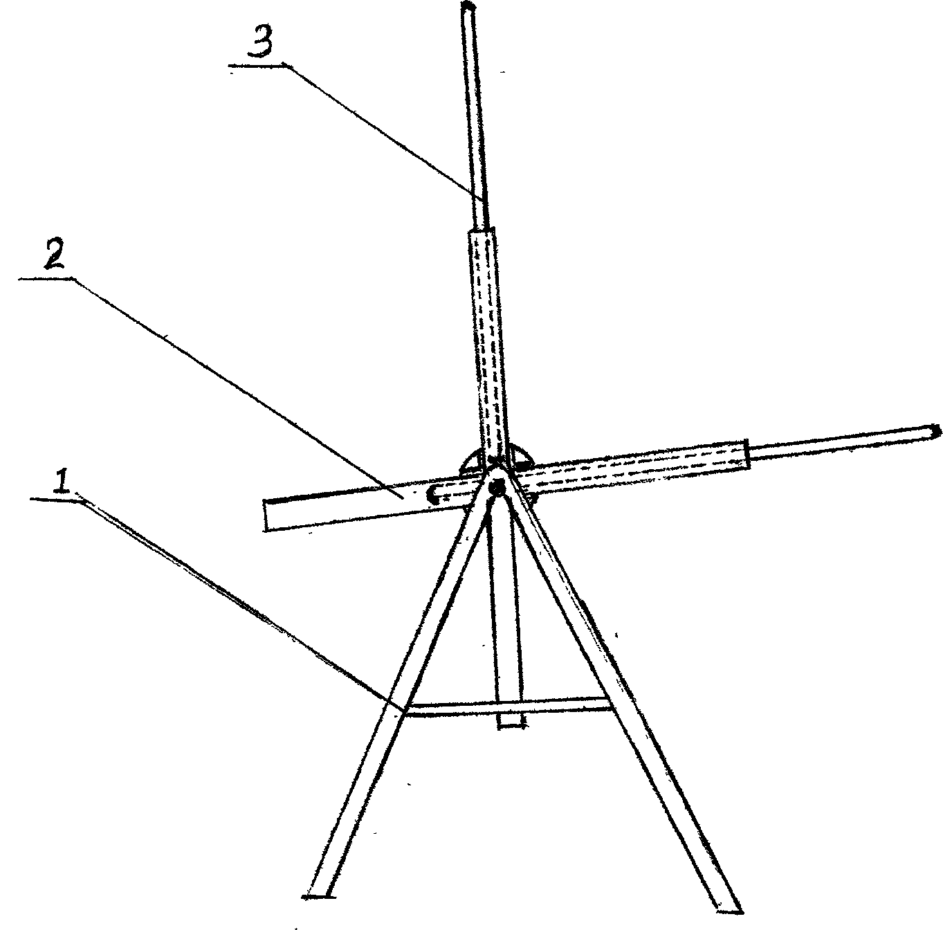
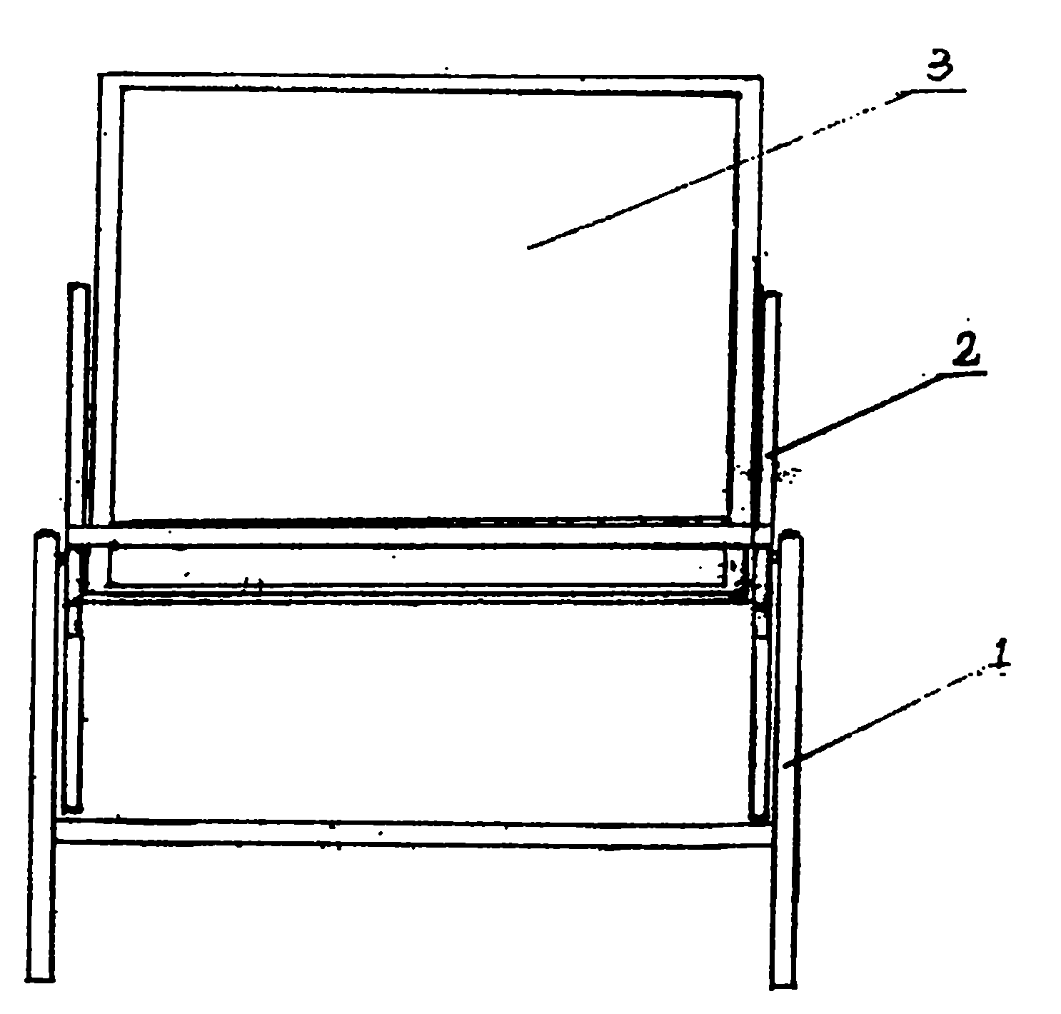
[0062] Embodiment 3: Horizontal axis rotating device
[0063] 1. Make two square frames according to the design requirements, and seal the space in the frame with airtight high-strength fabric to make it a movable leaf plate in this embodiment;
[0064] 2. Install the four channel steels on a set of opposite sides of the two blades to make them slide rails on the blades;
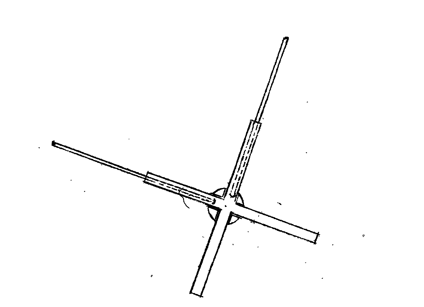
[0065] 3. Make two crossed crosses with T-shaped steel of suitable size, and install some pulleys on the crosses, and weld the two ends of the four angle steels with the four 90-degree top angles of the two crosses to make it a basic The hollow rotating skeleton of embodiment;
[0066] 4. Use round steel of suitable size to make two legs of A-type, and fix or weld them at the 1 / 2 height of the two legs, and then install the rotating skeleton on the vertices of the two legs to make it a basic The ridge-shaped stable frame of the rotating device (the rotating frame should be able to rotate on it);
[0067] ...
PUM
| Property | Measurement | Unit |
|---|---|---|
| Diameter | aaaaa | aaaaa |
Abstract
Description
Claims
Application Information
 - R&D
- Intellectual Property
- Life Sciences
- Materials
- Tech Scout
- Unparalleled Data Quality
- Higher Quality Content
- 60% Fewer Hallucinations
Browse by: Latest US Patents, China's latest patents, Technical Efficacy Thesaurus, Application Domain, Technology Topic, Popular Technical Reports.
© 2025 PatSnap. All rights reserved.Legal|Privacy policy|Modern Slavery Act Transparency Statement|Sitemap|About US| Contact US: help@patsnap.com