Piston compressor

A compressor and piston technology, applied in the field of piston compressors, can solve problems such as cylinder sealing

Active Publication Date: 2012-10-17
J P SAUER & SOHN MASCHB
View PDF9 Cites 0 Cited by
  • Summary
  • Abstract
  • Description
  • Claims
  • Application Information

AI Technical Summary

Problems solved by technology

However, cast iron pistons have the disadvantage that unwanted clearances can appear due to different coefficients of thermal expansion, and sealing problems can occur in the cylinder if the cylinder is not made of cast iron

Method used


Image

  • Piston compressor
  • Piston compressor
  • Piston compressor

Examples


Embodiment Construction

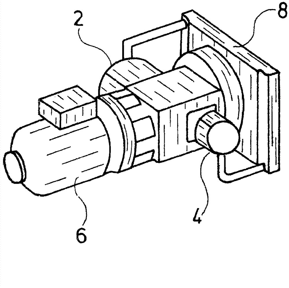
[0028] figure 1 The basic structure of a reciprocating compressor is shown, the reciprocating compressor shown here being of a two-stage type with two cylinders 2 and 4 . Pistons arranged in cylinders are driven by electric motor 6 via a common shaft. However, other drives can also be used, for example internal combustion engines. The cylinder 2 constitutes the first stage of the piston compressor, the gas compressed in the cylinder 2 being conveyed to the second stage via an intercooler 4 . exist figure 1 As can be seen in the figure, cylinder 4 of the second stage is smaller than cylinder 2, that is to say has a smaller working volume inside it, since the gas entering cylinder 4 has already been compressed in the first stage, cylinder 2. Correspondingly, the diameter of the second-stage piston 10 is also smaller than that of the first-stage piston.

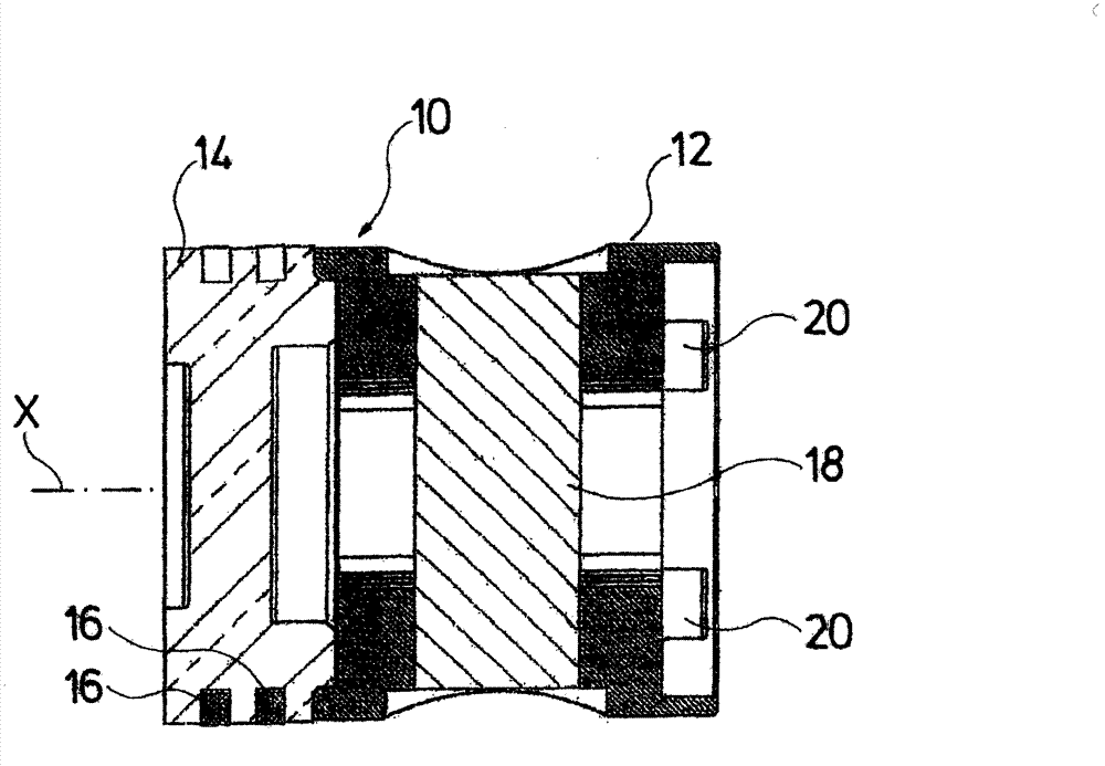
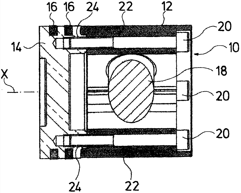
[0029] figure 2 and image 3 The structure of the piston 10 used in the second cylinder 4 in the second stage is shown....


PUM


Abstract

A piston compressor with one or more pistons (10). The at least piston (10) is a multi-part piston including at least one first part (12) and a second part (14). The first and second parts are manufactured of different materials.

Description

technical field [0001] The invention relates to a piston compressor with one or more pistons. Background technique [0002] For piston compressors, it is known to use multi-stage piston compressors in order to achieve higher pressures, in which the compression is achieved step by step in successively arranged cylinders. Since the volume decreases during compression, the working volume decreases step by step. To do this, the diameter of the piston and cylinder will usually be reduced. Pistons with a smaller diameter also have a lower weight, as a result of which imbalances and vibrations occur when all pistons are driven via a common crankshaft. Therefore, efforts are made to achieve a mass balance between the individual pistons. For this purpose, it is known, for example, to manufacture a first larger piston from aluminum and a second smaller piston from iron. However, cast iron pistons have the disadvantage that unwanted clearances can appear due to different coefficien...

Claims


Application Information

Patent Timeline
Patent Type & Authority Applications(China)
IPC IPC(8): F04B39/00
CPCF04B53/14F04B39/0005F05C2201/021F05C2201/0448
Inventor 彼得·米斯费尔特彼得·达姆斯沃尔夫冈·维格斯
Owner J P SAUER & SOHN MASCHB
Why Eureka
Try Eureka