
Circuit and method for detecting remaining power of motor drive controller of electric vehicle

A motor drive and controller technology, applied in the direction of measuring current/voltage, measuring resistance/reactance/impedance, instruments, etc., can solve the problems of endangering personal and vehicle safety, inability to accurately detect residual electricity of capacitors, poor stability, etc., to achieve Improve the warning effect, broaden the detection range, and have high practical effects

Active Publication Date: 2012-10-24
DONGFANG ELECTRIC CORP LTD
View PDF7 Cites 2 Cited by
  • Summary
  • Abstract
  • Description
  • Claims
  • Application Information

AI Technical Summary

Problems solved by technology

[0003] After analysis, the traditional residual electricity detection method is to connect tens of thousands of ohms to hundreds of kiloohms of resistors and light-emitting diodes in series at both ends of the capacitor. When the capacitor has residual electricity, the electricity in the capacitor drives the light-emitting diodes. Lights up to warn the operator, and in order to enhance the intuitiveness and convenience, most of the prompting

Method used


Image

  • Circuit and method for detecting remaining power of motor drive controller of electric vehicle
  • Circuit and method for detecting remaining power of motor drive controller of electric vehicle
  • Circuit and method for detecting remaining power of motor drive controller of electric vehicle

Examples


Example Embodiment

[0034] Example 1

[0035] Such as figure 1 As shown, the voltage across the capacitor connected in parallel to the main circuit U IN The range of change is 0~600VDC, applied to the input resistance R IN =300kΩ, the current I generated in the primary circuit of the voltage sensor IN 0~2mA, the voltage sensor primary and secondary coil transformation ratio is 2.5, namely k 1 =2.5, the output current I in the secondary coil O The variation range is 0~5mA, the output current I in the secondary coil O Flow through the conditioning resistor R in the secondary loop 1 =500Ω, the generated voltage U 1 Is 0~2.5V, the voltage U 1 After bias adjustment, it is converted into a suitable range 0.3V~2.8V that can be collected by MCU, which is the bias voltage U of the bias circuit 3 =0.3V.

[0036] Such as figure 2 As shown, the signal transmission between the MCU and the prompting device adopts an isolation method, and the power supply of the prompting device also adopts a power supply isolated ...

Example Embodiment

[0044] Example 2

[0045] Such as figure 1 As shown, the voltage U across the capacitor connected in parallel on the main circuit IN The range of change is 0~1000V, applied to the input resistance R IN =100kΩ, the current I generated in the primary circuit of the voltage sensor IN 0~10mA, the voltage sensor primary and secondary coil transformation ratio is 2, namely k 1 =2, the output current I in the secondary coil O The variation range is 0-20mA, the output current I in the secondary coil O Flow through the conditioning resistor R in the secondary loop 1 =100Ω, the generated voltage U 1 0~2V, the bias circuit generates 0.2V, that is, the output voltage range of the bias circuit is 0.2~2.2V, the output voltage of the bias circuit is amplified by the linear conversion circuit twice and the output voltage is suitable for the MCU to collect The range is 0.4V~4.4V.

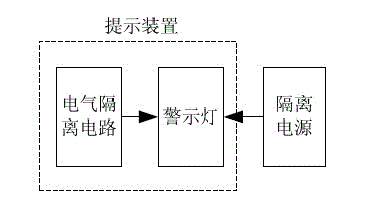
[0046] Such as figure 2 As shown, the signal transmission between the MCU and the prompting device adopts an isolat...


PUM


Abstract

The invention relates to remaining power detection technologies, in particular to a circuit and a method for detecting the remaining power of a motor drive controller of an electric vehicle. The circuit comprises a voltage sensor, a conditioning circuit, an MCU (Micro Controller Unit) and a prompting device, wherein the voltage sensor is connected with the conditioning circuit, the conditioning circuit is connected with the MCU, the MCU is connected with the prompting device, the voltage at the two terminals of a capacitor is acquired through an electrical isolation manner of the voltage sensor, the acquired signals are quickly subjected to processing and logical judgment by adopting the MCU, and a prompting signal indicating whether the remaining power of the capacitor is within a safety range or not is output by using the electrical isolation manner. According to the circuit and the method, the high-voltage remaining power remained in the capacitor can be effectively, accurately and reliably detected, so that an applicable range of remaining power voltage detection is widened, the anti-interference capability is higher, the structure is simple, the practicability is high, and the harmfulness on human bodies and the vehicles caused by the remaining power is effectively reduced.

Description

technical field [0001] The invention relates to residual electricity detection technology, in particular to an electric vehicle motor drive controller residual electricity detection circuit and method. Background technique [0002] At present, the electric vehicle industry is developing vigorously. Electric vehicles have become the future development direction of the automobile industry due to their green advantages. However, there are still many technical bottlenecks restricting the industrialization and commercialization of electric vehicles. Among them, the electric drive system is One of the outstanding factors restricting the development of electric vehicles, the safe, stable and efficient operation of the electric drive system is the most critical factor affecting the overall performance of electric vehicles. Parallel capacitors in the main circuit of the electric drive system can effectively ensure the safe, stable and efficient operation of the electric drive system,...

Claims


Application Information

Patent Timeline
IPC IPC(8): G01R19/00G01R27/26
Inventor 任亚辉郑刚蒲晓珉张登
Owner DONGFANG ELECTRIC CORP LTD
Learn More