

Anti-collision pier for mountainous area curve
A technology of anti-collision piers and curves, which is applied in the direction of roads, roads, road signs, etc., can solve the problems of not being able to play a good warning role, numbness of light reflected by warning strips, poor reflection effect of warning strips, etc., and achieve good Luminous effect, improve warning effect, improve warning effect
- Summary
- Abstract
- Description
- Claims
- Application Information
AI Technical Summary
Problems solved by technology
Method used
Image

Examples
Embodiment 1
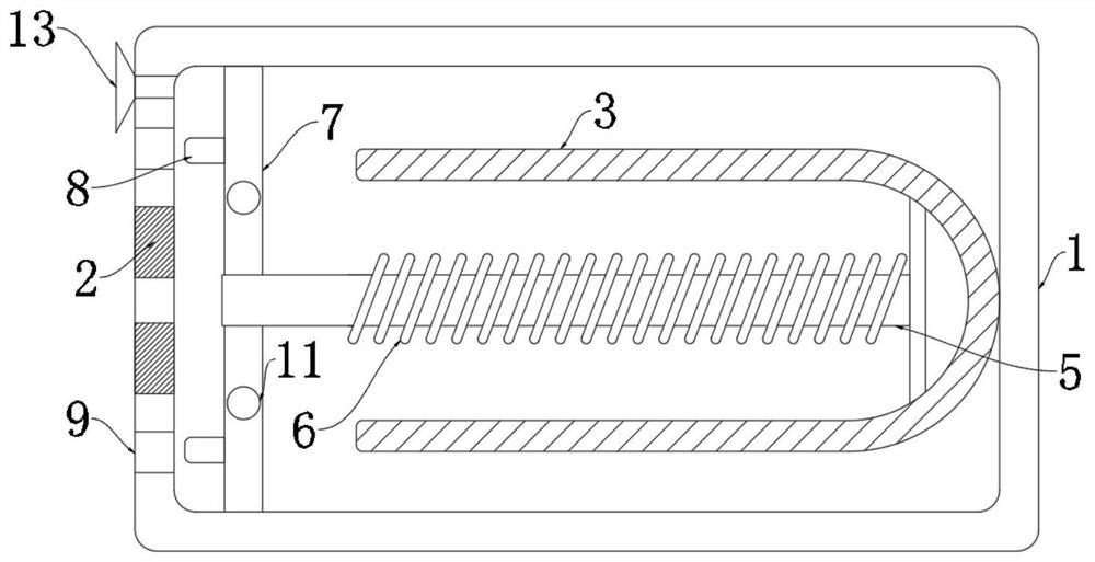
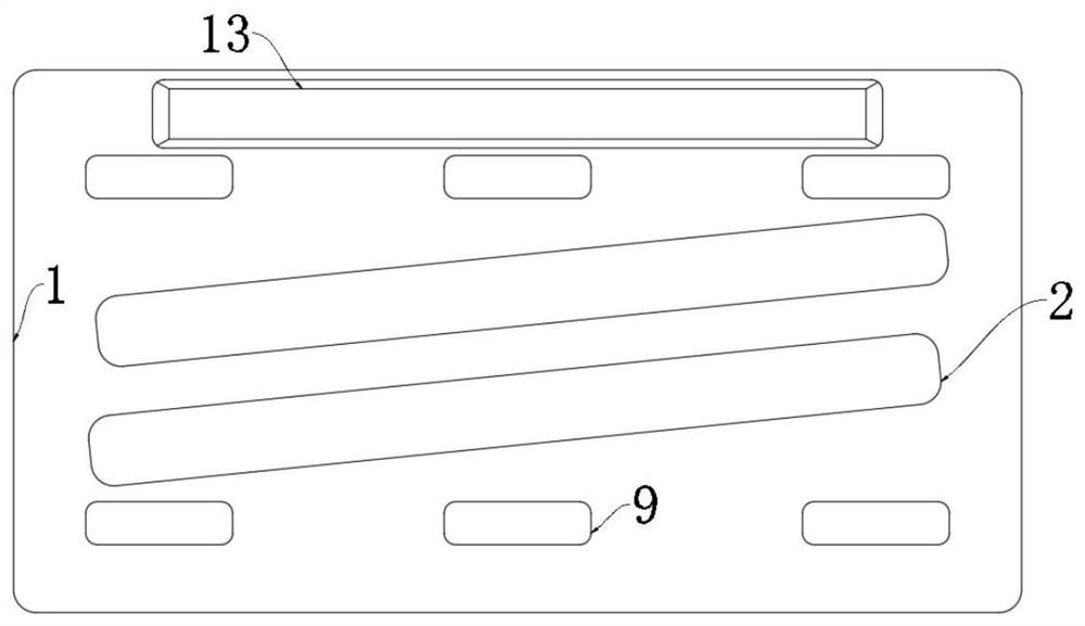
[0038] refer to Figure 1-3 , an anti-collision pier for mountainous curves, including an anti-collision pier body 1 which is hollow inside, and two warning strips 2 are embedded on the outer wall of the anti-collision pier body 1, when the car light hits the warning strip 2 , the reflection of the warning strip 2 plays a warning role;
[0039] A plurality of U-shaped magnets 3 are fixedly connected to the inner wall of the anti-collision pier body 1;
[0040] The U-shaped magnet 3 is fixedly connected with a vibrating rod 5, and the side wall of the vibrating rod 5 is wound with a multi-turn coil 6;
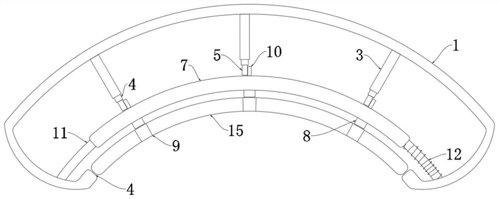
[0041] The anti-collision pier body 1 is provided with an arc-shaped mouth 4, and an arc-shaped baffle 15 is arranged inside the arc-shaped mouth 4;
[0042] The anti-collision pier body 1 is fixedly connected with a first guide rod 11, and the first guide rod 11 is provided with an arc-shaped plate 7, and a plurality of indicator lights 8 are fixedly connected to the arc-shap...
Embodiment 2
[0049] refer to Figure 4-5The difference between this embodiment and Embodiment 1 is that a second guide rod 14 is fixedly connected to the opposite inner wall of the arc-shaped mouth 4, and the second guide rod 14 runs through the arc-shaped baffle plate 15; the left end of the second guide rod 14 A second spring 16 is sheathed, and the second spring 16 is fixedly connected to the left side wall of the arc-shaped baffle 15; the multi-turn coil 6 is electrically connected to the second spring 16 through a pulser, and the pulser makes the second spring 16 The intermittent on-off of the current in the arc-shaped baffle plate 15 is in the process of rapid reciprocating movement, and its moving frequency is inconsistent with the moving frequency of the arc-shaped plate 7, so that the frequency of the indicator light 8 passing through the light-transmitting hole 9 is faster, thereby Further increase the flashing frequency, and this process increases the moving range of the arc-sha...
PUM
 Abstract
Description
Claims
Application Information