Fault injection system for intelligent bus

A bus fault injection system technology, applied in instruments, electrical digital data processing, computing, etc., can solve problems such as jitter, achieve the effect of avoiding jitter and improving test efficiency

Active Publication Date: 2012-10-24
ZHEJIANG GEELY AUTOMOBILE RES INST CO LTD +1
View PDF9 Cites 16 Cited by
  • Summary
  • Abstract
  • Description
  • Claims
  • Application Information

AI Technical Summary

Problems solved by technology

[0006] The present invention mainly solves the technical problem of jitter caused by manually injecting faults into the CAN bus in the prior art, and provides an intelligent bus fault injection system that can accurately realize automatic fault injection and no jitter for the automotive CAN bus

Method used


Image

  • Fault injection system for intelligent bus
  • Fault injection system for intelligent bus

Examples


Embodiment

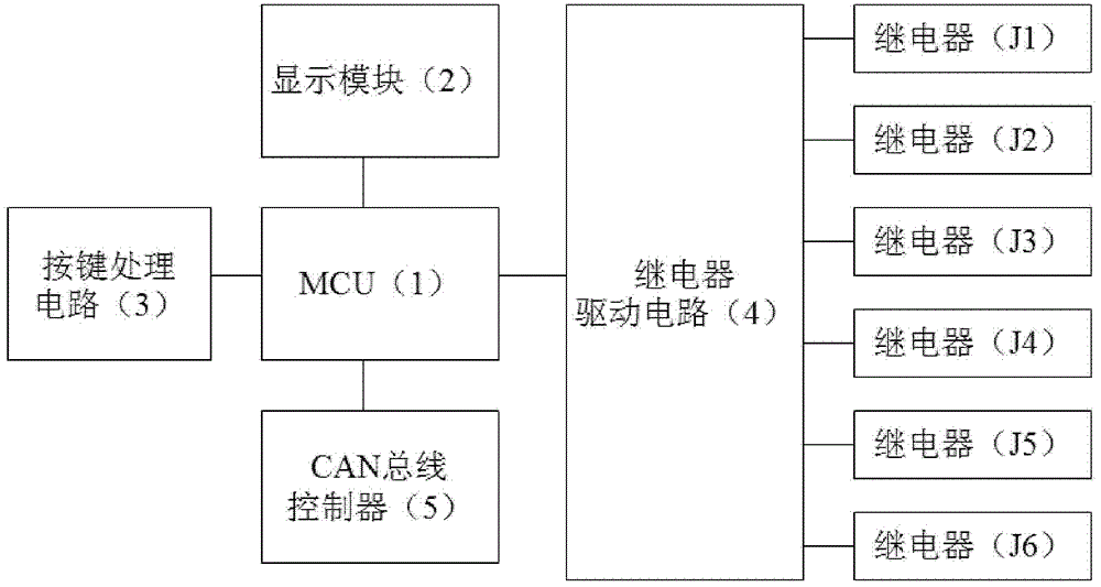
[0024] Embodiment: A kind of intelligent bus fault injection system of this embodiment, such as figure 1 As shown, it includes button processing circuit 3, MCU1, relay drive circuit 4, display module 2, and several relays. The entire system is powered by a power supply circuit. The control end of the relay is electrically connected to MCU1 through the relay drive circuit 4. The controlled end of the relay It is connected with the CAN bus of the automobile, the key processing circuit 3 and the display module 2 are respectively electrically connected with the MCU1, and the MCU1 is connected with the CAN bus controller 5 of the automobile.

[0025] The key processing circuit 3 includes a confirmation key, a channel selection key, a time configuration key, an increase key, a decrease key and a reset key. The channel selection key is used to select different fault types, and the time configuration key is used to set the injection time. Through the cooperation of the above keys, di...


PUM


Abstract

The invention discloses a fault injection system for an intelligent bus and aims at providing a test system capable of automatically injecting faults. The fault injection system comprises a key processing circuit, a microprogrammed control unit (MCU), a relay driving circuit, a display module, a plurality of relays and a power circuit for providing power for the whole system. Control ends of the relays are electrically connected with the MCU through the relay driving circuit, controlled ends of the relays are connected with an automobile controller area network (CAN) bus, the key processing circuit and the display module are electrically connected with the MCU respectively, and the MCU is connected with an automobile CAN bus controller. Detection personnel inject parameters of faults through the key processing circuit. The MCU utilizes the relay driving circuit to control the relays to inject the faults into the automobile bus and receives signals fed back by the CAN bus controller. By means of the relays serving as fault injection ends, shaking generated by manual injection is avoided. The fault injection system is suitable for detecting stability of the automobile CAN bus.

Description

[0001] technical field [0002] The invention relates to a fault testing device, in particular to an intelligent bus fault injection system for detecting the reliability and stability of the CAN bus of an automobile. Background technique [0003] With the continuous increase of automobile functions, more and more electronic control units (ECUs) are introduced into automobiles. The requirements are getting higher and higher, and higher requirements are put forward for the stability and reliability of the CAN bus system. Therefore, the verification of bus stability and reliability is becoming more and more important. Conventional bus reliability verification directly uses tools such as wires and sliding rheostats to manually inject faults. [0004] The verification of bus reliability includes tests such as bus short circuit, open circuit, and node communication loss. In the past, bus reliability tests were conducted by manually disconnecting the CAN-H line and CAN-L line, o...

Claims


Application Information

Patent Timeline
Patent Type & Authority Applications(China)
IPC IPC(8): G06F11/267
Inventor 葛丽敏王建磊傅立骏熊想涛陈文强潘之杰赵福全
Owner ZHEJIANG GEELY AUTOMOBILE RES INST CO LTD
Why Eureka
Try Eureka