Flywheel array energy storage system with flywheel energy storage units connected in parallel

A flywheel energy storage and energy storage system technology, which is applied in the field of high-power flywheel array energy storage systems, can solve the problems of system limitations, the inability to directly use DC power grids for power supplies, and the inability to freely add flywheel energy storage units to improve energy storage efficiency. Effect

Inactive Publication Date: 2012-10-24
INST OF ELECTRICAL ENG CHINESE ACAD OF SCI
View PDF5 Cites 37 Cited by
  • Summary
  • Abstract
  • Description
  • Claims
  • Application Information

AI Technical Summary

Problems solved by technology

This kind of power supply cannot be directly used in the DC grid, and the capacity of the system is limited by the grid-connected inverter, and new flywheel energy storage units cannot be freely added

Method used


Image

  • Flywheel array energy storage system with flywheel energy storage units connected in parallel
  • Flywheel array energy storage system with flywheel energy storage units connected in parallel
  • Flywheel array energy storage system with flywheel energy storage units connected in parallel

Examples


Embodiment Construction

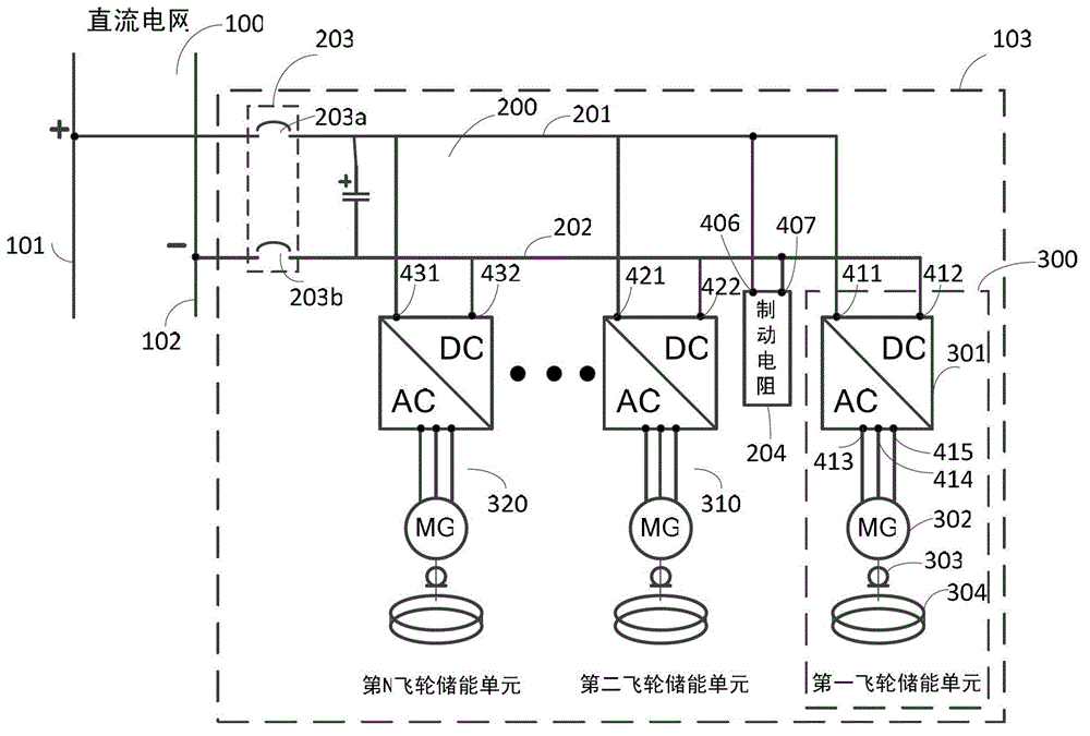
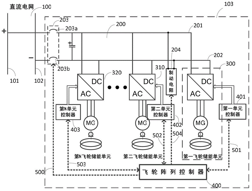
[0020] figure 1 It is a schematic diagram of the flywheel array energy storage system of the present invention. A flywheel array energy storage system 103 that can be directly integrated into a DC grid 100 is composed of a common DC bus 200, a grid-connected static switch 203, a braking resistor 204, and more than two flywheel energy storage units and their unit controllers . Wherein, the common DC bus 200 is composed of a positive bus 201 and a negative bus 202 , and the two DC-side outlets of each flywheel energy storage unit are respectively connected to the positive and negative buses of the common DC bus 200 . For example, the first lead-out end 411 and the second lead-out end 412 of the DC side of the first flywheel energy storage unit 300 are respectively connected to the positive bus 201 and the negative bus 202 of the common DC bus 200; The lead-out 421 and the second lead-out 422 are respectively connected to the positive bus 201 and the negative bus 202 of the com...


PUM


Abstract

The invention relates to a flywheel array energy storage system with flywheel energy storage units connected in parallel, which consists of a public direct current bus, a grid-connected static switch, a brake resistor, a flywheel array controller and at least two or more flywheel energy storage units and unit controllers thereof, wherein the internal structures and parameter features of the flywheel energy storage units are identical. Each flywheel energy storage unit is connected into the public direct current bus in a current source mode, and the number of the connected units can be increased and decreased casually. A master-slave control mode is adopted in the flywheel array energy storage system disclosed by the invention, power needed for maintaining direct current power grid power balance is computed by the flywheel array controller used as a master controller, and the power is distributed to each flywheel energy storage unit controller by a coordination control algorithm; and a bi-directional power conversion circuit and a permanent magnet synchronous motor are controlled by the unit controller used as a slave controller according to the obtained power instruction in a flywheel energy storage unit control method to absorb or release power to a direct current power grid.

Description

technical field [0001] The invention relates to a high-power flywheel array energy storage system for grid-level applications. Background technique [0002] Flywheel energy storage is an energy storage technology that stores electrical energy in the form of mechanical energy in a high-speed rotating flywheel rotor. It is generally composed of a flywheel rotor, a supporting bearing, a motor, a protective casing, and a power conversion circuit. According to the working speed of the flywheel rotor, it can be divided into high-speed flywheel energy storage system and low-speed flywheel energy storage system. The former uses composite material rotor and magnetic suspension bearing, and the working speed is tens of thousands of rpm; the latter uses metal material rotor and mechanical bearing. , The working speed is generally several thousand rpm. According to relevant data in the field of flywheel energy storage technology at home and abroad, the rated output power of an independ...

Claims


Application Information

Patent Timeline
Patent Type & Authority Applications(China)
IPC IPC(8): H02J1/16
Inventor 周龙唐西胜刘文军齐智平
Owner INST OF ELECTRICAL ENG CHINESE ACAD OF SCI
Why Eureka
Try Eureka