
Active signal enhancer and radio frequency identification system thereof

A technology of radio frequency identification system and booster, which is applied in the field of radio frequency identification, can solve the requirements of carrier signal, reader field strength and receiving sensitivity, cannot realize reader mode and end-to-end mode, and mobile devices cannot establish reliable communication and other issues to achieve the effect of expanding the scope of application

Inactive Publication Date: 2012-10-24
SHANGHAI QUANRAY ELECTRONICS
View PDF3 Cites 5 Cited by
  • Summary
  • Abstract
  • Description
  • Claims
  • Application Information

AI Technical Summary

Problems solved by technology

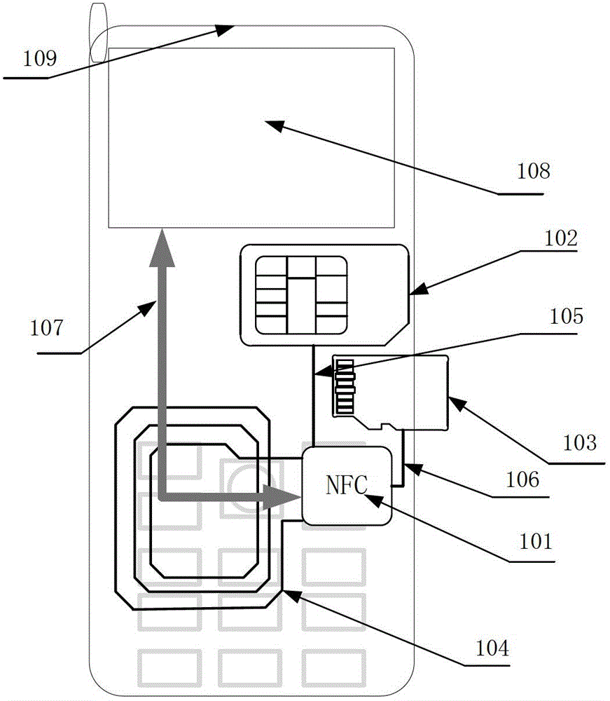
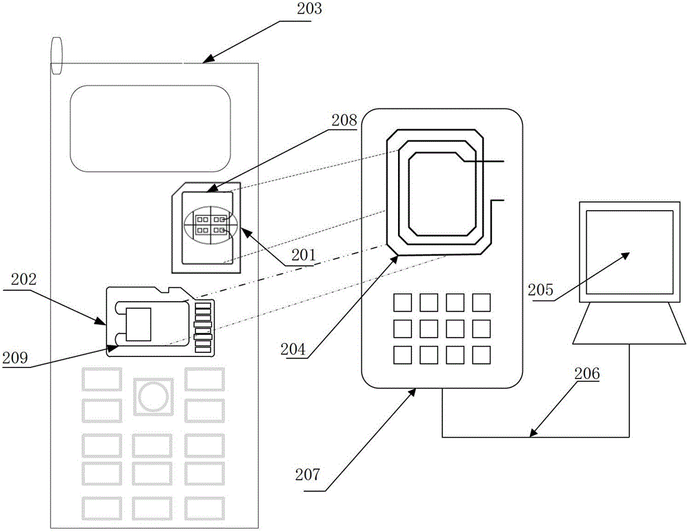
Due to the shielding of mobile communication equipment batteries, circuit boards, back covers, card slots, etc., the modulated signal of the reader and the reflected modulated signal of the dual-interface SIM card or dual-interface SD card are severely attenuated. Under the received signal amplitude index, many mobile devices cannot establish reliable communication
Limited by the antenna area of ​​the dual-interface SIM card or dual-interface SD card, and the shielding of the battery, circuit board, back cover, card slot, etc. of the mobile communication device, it is also difficult to transmit the carrier signal through the dual-interface SIM card or dual-interface SD card. It meets the requirements of standard reader field strength and receiving sensitivity. This structure cannot realize the standard reader mode.
Therefore, the dual-interface SIM card or dual-interface SD card full card solution can only support some mobile communication devices to realize the tag mode in near field communication, but cannot realize the reader mode and end-to-end mode

Method used


Image

  • Active signal enhancer and radio frequency identification system thereof
  • Active signal enhancer and radio frequency identification system thereof
  • Active signal enhancer and radio frequency identification system thereof

Examples


Embodiment Construction

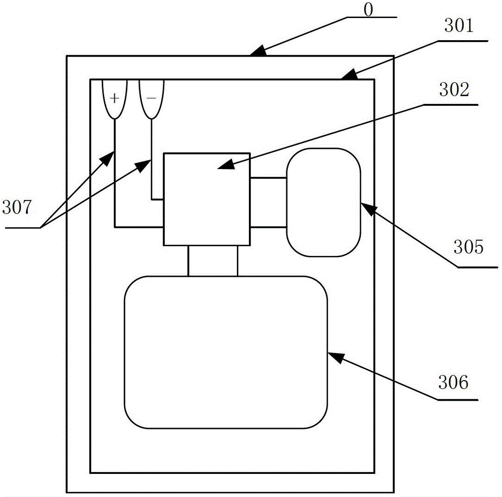
[0052] refer to image 3 , the embodiment of the present invention provides an active signal booster 0, including: a booster card base 301, a non-contact receiving matched filter antenna 305, a non-contact transmitting matched filtering antenna 306, a battery power supply lead 307 and a chip 302; Wherein, the chip 302 is connected to the non-contact receiving matched filter antenna 305, and the non-contact transmitting matched filtering antenna 306 is directly connected or connected through a matching network; the described battery power lead 307 is connected to the battery power contact of the mobile communication device .

[0053] The chip 302 includes an RF interface module, and the RF interface module at least includes a receiving amplification and filtering unit, a demodulation unit, a modulation unit, a transmission power amplification unit, a logic control module and a power supply module.

[0054] refer to Figure 5 , the receiving amplification filtering unit 501 of...


PUM


Abstract

An active signal enhancer comprises a card base, a battery power supply lead, a chip which is embedded inside the card base, a noncontact receiving matching filter antenna and a noncontact transmitting matching filter antenna, wherein the chip is connected with a battery power supply of a mobile communication device through the battery power supply lead; the noncontact receiving matching filter antenna and the noncontact transmitting matching filter antenna are directly connected onto the chip; and the chip is used for demodulating an amplified signal received by the noncontact receiving matching filter antenna, or the signal to be transmitted is transmitted to the noncontact transmitting matching filter antenna after a carrier is modulated. Due to the adoption of the active signal enhancer and the radio frequency identification system thereof, a near field communication (NFC) controller on the mobile communication device is eliminated, a physical connection wire and an NFC antenna contact between a subscriber identifier module (SIM) card or a security digital (SD) card and an NFC controller can be eliminated, three modes of the noncontact near field communication can be realized, the structures of a reader and the mobile communication device are unnecessary to modify.

Description

technical field [0001] The invention relates to radio frequency identification technology, in particular to an active signal enhancer and a radio frequency identification system thereof. Background technique [0002] After more than ten years of development, radio frequency identification technology (Radio Frequency Identification, hereinafter referred to as RFID) technology, including contactless integrated circuit card (Integrated Circuit Card, IC card for short), has penetrated into every corner of modern life and is widely used in Public transportation, access control, small electronic payment and other fields. [0003] Radio frequency identification technology is a kind of automatic identification technology. The composition of radio frequency identification system generally includes at least two parts: electronic tag (Tag) and reader (Reader). Electronic tags are used to store electronic data in an agreed format. In practical applications, electronic tags can be attac...

Claims


Application Information

Patent Timeline
Patent Type & Authority Applications(China)
IPC IPC(8): H04B1/38H04B5/02G06K19/077G06K7/00H04B7/15
Inventor 朱正
Owner SHANGHAI QUANRAY ELECTRONICS
Learn More