
On-line electric energy quality monitoring device

A technology for power quality monitoring and power quality, which is applied to measuring devices, measuring electrical variables, measuring electricity, etc. It can solve the problems of damage to devices and equipment, only reaching about 80 μs, and unable to collect transient signals and transient signals.

Active Publication Date: 2012-10-31
深圳市中电软件有限公司
View PDF7 Cites 24 Cited by
  • Summary
  • Abstract
  • Description
  • Claims
  • Application Information

AI Technical Summary

Problems solved by technology

[0002] Non-linear loads and impact loads of the power system, including transient disturbances such as the connection of equipment on the power grid and lightning strikes, and the operation of reactive loads on the same circuit at the user site, often cause damage to devices and equipment connected to the line. serious damage
Since the duration of transient interference is much shorter than the 20ms power supply cycle, and the transient voltage is several times or even dozens of times the rated voltage of the power system, the sampling rate of the existing power quality device is 128, 256 points / cycle, and the measurement range is narrow. Even if the sampling rate is 512 points / cycle, its transient capture ability can only reach about 80μs, so it is often impossible to collect transient signals or to truly and completely record the transient signals at that time
If the power quality device uses a high sampling rate throughout the whole process, it is unnecessary to monitor and analyze conventional power quality indicators such as voltage deviation, frequency deviation, harmonics, flicker, unbalance, etc., and its software implementation is too difficult, and hardware costs also too high

Method used


Image

  • On-line electric energy quality monitoring device

Examples


Embodiment Construction

[0033] The present invention will be described below in combination with specific embodiments and with reference to the accompanying drawings.

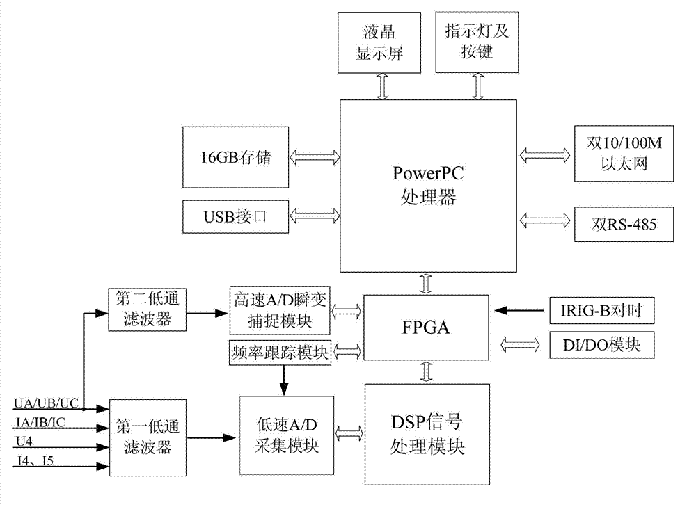
[0034] An on-line power quality monitoring device for capturing high-speed voltage transients as shown in the accompanying drawing, the hardware platform is an embedded hardware platform, which adopts a complex architecture including Power PC functional units, FPGA functional units, and DSP functional units, The Power PC functional unit and the DSP functional unit are independent of each other, and the Power PC functional unit performs data interaction with the DSP functional unit through the dual-port RAM configured inside the FPGA functional unit, and is used to analyze and count the calculation results uploaded by the DSP functional unit, Manage storage, communication transmission, human-computer interaction, and remote control.

[0035] The DSP functional unit includes the first low-pass filter with a cut-off frequency of 12KHz, t...


PUM


Abstract

The invention discloses an on-line electric energy quality monitoring device. A hardware platform is an embedded hardware platform and is in a complex structure consisting of a Power PC (Personal Computer) functional unit, an FPGA (Field Programmable Gate Array) functional unit and a DSP (Digital Signal Processing) functional unit, wherein the Power PC functional unit is independent of the DSP functional unit; and data interaction is performed between the Power PC functional unit and the DSP functional unit through a double-port RAM (Random Access Memory) configured in the FPGA functional unit. The conventional normal electric energy quality device has a high-speed transient signal acquisition function by only increasing limited cost. The on-line electric energy quality monitoring device is widely applied to nonlinear load and impact load, including on-line monitoring of conventional electric energy quality index parameters at places with more serious transient interference such as equipment connection and lightning strike on a power grid; and when a high-speed voltage transient abnormal event occurs, the current transient signal can be automatically acquired and truly and completely recorded, and basis support is provided for failure analysis of devices and equipment on a power supply line.

Description

technical field [0001] The invention relates to electric energy measurement, in particular to an on-line electric energy quality monitoring device. Background technique [0002] Non-linear loads and impact loads of the power system, including transient disturbances such as the connection of equipment on the power grid and lightning strikes, and the operation of reactive loads on the same circuit at the user site, often cause damage to devices and equipment connected to the line. serious damage. Since the duration of transient interference is much shorter than the 20ms power supply cycle, and the transient voltage is several times or even dozens of times the rated voltage of the power system, the sampling rate of the existing power quality device is 128, 256 points / cycle, and the measurement range is narrow. Even if the sampling rate is 512 points / cycle, its transient capture ability can only reach about 80 μs, so it is often impossible to collect transient signals or to tru...

Claims


Application Information

Patent Timeline
Patent Type & Authority Applications(China)
IPC IPC(8): G01R31/00
Inventor 曾幼松张涛熊伟曾伟滕斌刘国良郭敏韦云云廖文国陈世奎
Owner 深圳市中电软件有限公司
Learn More