LED lamp for tunnel illumination and mounting method of LED lamp

A technology for LED lamps and tunnel lighting, which is applied to lighting devices, fixed lighting devices, and parts of lighting devices. Reduce the light intensity and solve the effect of glare problem

Inactive Publication Date: 2012-11-07
重庆楚商光电科技有限公司
View PDF8 Cites 11 Cited by
  • Summary
  • Abstract
  • Description
  • Claims
  • Application Information

AI Technical Summary

Problems solved by technology

[0005] One of the purposes of the present invention is to provide an LED lamp for tunnel lighting, so that it can solve the defects of existing lamps such as high installation position, high energy consumption and easy glare. The specific technical solution is as follows:

Method used


Image

  • LED lamp for tunnel illumination and mounting method of LED lamp
  • LED lamp for tunnel illumination and mounting method of LED lamp
  • LED lamp for tunnel illumination and mounting method of LED lamp

Examples


Embodiment Construction

[0024] The present invention will be further described below in conjunction with the accompanying drawings and specific embodiments.

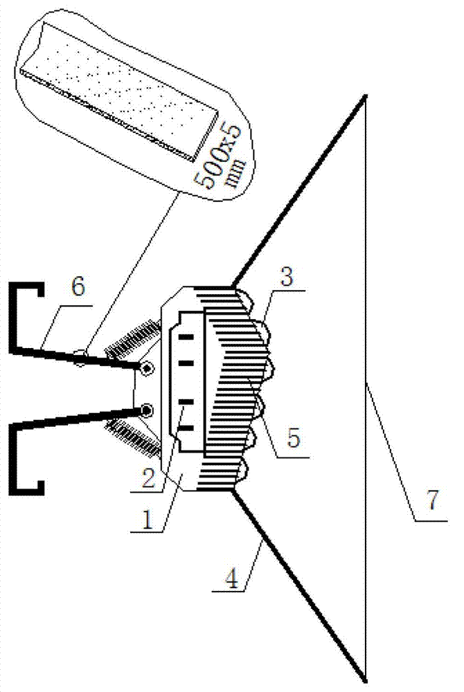
[0025] Such as figure 2 Shown: an LED lamp for tunnel lighting, including a lamp stand 1, a built-in power supply 2, an LED luminous part 3 and a lampshade 4, the built-in power supply 2 and the LED luminous part 3 are installed in the lamp stand 1, and the lampshade 4 covers the lamp On the frame 1, the LED light-emitting part 3 is a folded light-emitting board equipped with an array of LED lamp beads. The number of lamp beads on the upper surface of the folded-shaped light-emitting board is smaller than that of the lower face. A cooling plate 5 is also attached to improve the heat dissipation performance of the lamp. In order to protect the internal structure of the lamp, a lens 7 is arranged at the front edge of the lampshade 4, and the sealing of the lens 7 can also achieve a dustproof effect.

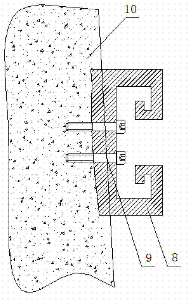
[0026] In order to facilitate the installat...


PUM


Abstract

The invention discloses an LED lamp for tunnel illumination and a mounting method of the LED lamp. The LED lamp comprises a lamp support, a built-in power supply, an LED illuminating piece and a lamp cover. The built-in power supply and the LED illuminating piece are mounted in the lamp support, and the lamp cover is covered on the lamp support. The LED lamp for tunnel illumination is characterized in that the LED illuminating piece is a fold-type illuminating slab mounted with an LED lamp ball array. Rails are transversely fixed on walls on two sides of a tunnel via expansion bolts, spring clips of the LED lamp are connected in the rails in snap-fit manner, and illumination intensity in the tunnel can be adjusted by adjusting the distance between adjacent two LED lamps via sliding the spring clips. The LED lamp for tunnel illumination is simple in structure and convenient to mount and maintain, and by designing lights emitted in two directions, flare problem in the tunnel is solved, mounting height of the lamp is changed simultaneously, illumination intensity is reduced, and energy consumption is saved.

Description

technical field [0001] The invention relates to an LED lamp, in particular to an LED lamp for tunnel lighting and an installation method thereof. Background technique [0002] The tunnel is a special tubular structure. Different from the bright and spacious road outside the cave, vehicles entering and exiting the tunnel during the day is a process from bright to black hole, and from black hole to bright. There are several special visual problems in this process: (1) When the vehicle enters the tunnel during the day, a "black hole effect" will appear at the entrance of the tunnel; (2) After entering the tunnel, the driver's naked eyes need a certain amount of time to adapt to the light environment inside the tunnel, and there will be "adaptation lag phenomenon"; (3) At the exit of the tunnel, due to the extremely high brightness outside the tunnel, a "white hole effect" appears at the exit. Due to these special visual problems, extremely high lighting requirements are put fo...

Claims


Application Information

Patent Timeline
Patent Type & Authority Applications(China)
IPC IPC(8): F21S8/00F21V19/00F21W131/101F21Y101/02
Inventor 李述洲王兴龙胡刚
Owner 重庆楚商光电科技有限公司
Why Eureka
Try Eureka