Thermal infrared imager and correcting device and method thereof

A technology of an infrared thermal imager and a correction device, which is applied in the field of infrared imaging to achieve the effect of real-time correction parameter update and convenient real-time imaging

Inactive Publication Date: 2012-11-07
UNIV OF ELECTRONICS SCI & TECH OF CHINA
View PDF5 Cites 32 Cited by
  • Summary
  • Abstract
  • Description
  • Claims
  • Application Information

AI Technical Summary

Problems solved by technology

At this time, the thermal imager needs to be returned to the factory for recalibration with the bl

Method used


Image

  • Thermal infrared imager and correcting device and method thereof
  • Thermal infrared imager and correcting device and method thereof
  • Thermal infrared imager and correcting device and method thereof

Examples


Embodiment Construction

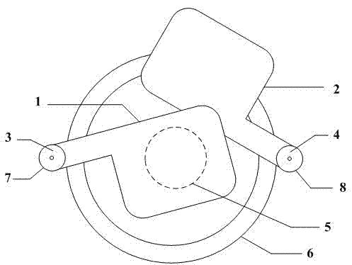
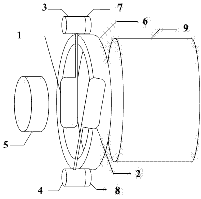
[0022] Such as figure 1 with figure 2 As shown, in an embodiment of the present invention, the infrared thermal imager includes a correction device of the infrared thermal imager, and the correction device is arranged in the infrared thermal imager and is a part of the infrared thermal imager.

[0023] In an embodiment of the present invention, the calibration device of the infrared thermal imager includes a first driving device 3, a first black body baffle 1, a second driving device 4, a second black body baffle 2 and a controller. The first black body baffle 1 is connected to the output end of the first driving device 3, and the first driving device 3 can drive the first black body baffle 1 to move; the second black body baffle 2 is connected to the output end of the second driving device 4. The second driving device 4 can drive the second black body baffle 2 to move; the first black body baffle 1 has a first temperature, and the second black body baffle 2 has a second temperat...


PUM


Abstract

An embodiment of the invention discloses a correcting device of a thermal infrared imager. The correcting device comprises a first driving device, a first black body blocking piece, a second driving device, a second black body blocking piece and a controller, wherein the first black body blocking piece is provided with a first temperature and connected to an output end of the first driving device; the second black body blocking piece is provided with a second temperature and connected to an output end of the second driving device; and the controller is connected to the first driving device and the second driving device, controls the first black body blocking piece to move between a first position and a second position, and controls the second black body blocking piece to move between a third position and a fourth position. According to the correcting device of the thermal infrared imager, the first black body blocking piece and the second black body blocking piece respectively move to the position between an infrared focal plane detector and an infrared lens to obtain a first infrared original image and a second infrared original image, so that correcting parameters of infrared images are obtained. Therefore, the correcting device can perform correcting parameter update on the thermal infrared imager in real time to adapt to different conditions and environment changes.

Description

[0001] technical field [0002] The invention relates to the field of infrared imaging, in particular to a calibration device and method for an infrared thermal imager and the infrared thermal imager. Background technique [0003] Infrared thermal imaging camera was developed in the late 1970s and early 1980s driven by national defense applications and other strategic and tactical applications. It is an important optoelectronic device for obtaining infrared thermal radiation information of scenery. In addition to being used in traditional situational imaging, infrared focal plane detectors are also widely used in industrial automation, medical diagnosis, chemical process detection, infrared astronomy and other fields. [0004] The non-uniformity of the infrared focal plane detector is due to the different output response characteristics of each detection unit of the infrared focal plane array, which results in the inconsistency of the output of each detection unit when the s...

Claims


Application Information

Patent Timeline
IPC IPC(8): G01J5/00
Inventor 刘子骥曾星鑫蔡贝贝杨书兵蒋亚东
Owner UNIV OF ELECTRONICS SCI & TECH OF CHINA
Why Eureka
Try Eureka