Method and device for automatically identifying MAC (Media Access Control) pin and ground pin of audio interface

An audio interface and automatic identification technology, applied in the field of electronics, can solve the problem of the audio signal sending device and the audio signal receiving device being unable to communicate normally, and achieve the effect of low cost and convenient subsequent use.

Active Publication Date: 2013-08-21
TENDYRON CORP
View PDF6 Cites 0 Cited by
  • Summary
  • Abstract
  • Description
  • Claims
  • Application Information

AI Technical Summary

Problems solved by technology

[0003] Due to the above-mentioned different types of audio interfaces, when the audio interface of the audio signal sending device is not connected to the ground pin of the audio interface of the audio signal receiving device, the audio signal sending device and the audio signal receiving device cannot communicate normally

Method used


Image

  • Method and device for automatically identifying MAC (Media Access Control) pin and ground pin of audio interface
  • Method and device for automatically identifying MAC (Media Access Control) pin and ground pin of audio interface
  • Method and device for automatically identifying MAC (Media Access Control) pin and ground pin of audio interface

Examples


Embodiment 1

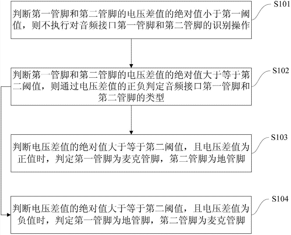
[0043] figure 1 Shows a flowchart of the method of automatically identifying the microphone pin and ground pin of the audio interface, see figure 1 , The method includes the following steps:

[0044] Step S101, judging that the absolute value of the voltage difference between the first pin and the second pin is smaller than the first threshold, and then not performing the identification operation on the first pin and the second pin of the audio interface;

[0045] Step S102, judging that the absolute value of the voltage difference between the first pin and the second pin is greater than or equal to the second threshold, and then judging the type of the first pin and the second pin of the audio interface based on the sign of the voltage difference;

[0046] Among them, the second threshold is greater than or equal to the first threshold; specifically, the range of the first threshold is generally 0-1V; preferably, the range of the first threshold is generally 0.4-0.6V, and further, th...

Embodiment 2

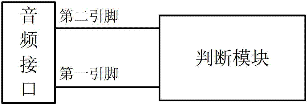
[0060] figure 2 Shows the schematic diagram of Embodiment 2 of the device for automatically identifying the microphone pin and ground pin of the audio interface, see figure 2 , The device for automatically identifying the microphone pin and the ground pin of the audio interface includes a judging module for judging that the absolute value of the voltage difference between the first pin and the second pin is less than the first threshold, Do not perform the recognition operation on the first pin and the second pin of the audio interface; when it is determined that the absolute value of the voltage difference between the first pin and the second pin is greater than or equal to the second threshold, the positive and negative of the voltage difference is passed Determine the type of the first pin and the second pin of the audio interface; where the second threshold is greater than or equal to the first threshold; when it is determined that the absolute value of the voltage differen...

Embodiment 3

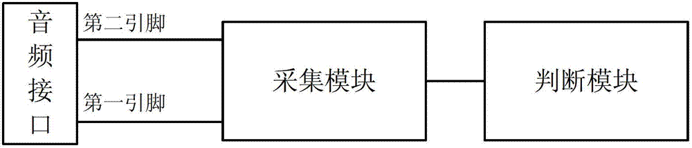
[0065] image 3 Shows a schematic diagram of Embodiment 3 of the device for automatically identifying the microphone pin and the ground pin of the audio interface, see image 3 In this embodiment, on the basis of embodiment 2, a collection module is added. The collection module is connected to the first pin and the second pin of the audio interface, and is used to collect the information of the first pin and the second pin. The voltage value or voltage difference value, and the voltage value or voltage difference value is sent to the judgment module.

[0066] Further, see Figure 4 The collection module may include a first collection module and a second collection module, wherein one end of the first collection module is connected to the first pin of the audio interface for collecting the voltage value of the first pin; One end is connected to the second pin of the audio interface for collecting the voltage value of the second pin; the other ends of the first collection module and...


PUM


Abstract

A method, device, and electronic signature tool for automatic identification of a microphone pin and a ground pin of an audio interface. The method comprises: if the absolute value of a voltage difference between a first pin and a second pin is determined to be less than a first threshold value, then not executing an identification operation; and, if the absolute value of the voltage difference between the first pin and the second pin is greater than or equal to a second threshold value, then determining the types of the first pin and of the second pin of the audio interface via the positivity / negativity of the voltage difference, where the second threshold value is greater than the first threshold value.

Description

Technical field [0001] The invention relates to the field of electronic technology, in particular to a method, a device and an electronic signature tool for automatically identifying the microphone pin and the ground pin of an audio interface. Background technique [0002] Existing audio signal sending equipment (for example, mobile communication terminal) audio interface (for example, earphone jack) and audio signal receiving equipment (for example, electronic signature tools, audio signal transfer equipment, and other audio output pins received and connected The audio interface of an audio signal receiving device that processes audio signals generally uses a four-segment interface, where the third pin and the fourth pin are audio output pins, that is, the left channel pin and the right channel pin. However, the functions of the first pin and the second pin of different audio interfaces are different. The first pin is the microphone pin MIC, the second pin is the ground pin GND,...

Claims


Application Information

Patent Timeline
Patent Type & Authority Patents(China)
IPC IPC(8): H04R3/00
CPCH04R2420/09H04R3/00H04R29/004H04R1/1041H04R2420/05H04R3/002
Inventor 李东声
Owner TENDYRON CORP
Why Eureka
Try Eureka