Roll stand

A technology of steel rolling frame and arch frame, which is applied in the field of rolling stainless steel, and can solve problems such as unguaranteed, interference, and unreliable

Active Publication Date: 2012-11-14
CLECIM SAS
View PDF11 Cites 5 Cited by
  • Summary
  • Abstract
  • Description
  • Claims
  • Application Information

AI Technical Summary

Problems solved by technology

Said separation is effected either by the operator, which is not reliable enough, or automatically, which cannot be ensured in the event of a failure of the control system of the rolling plant which guarantees said automation
[0020] The second disadvantage is that there is interference between the work rolls and the two side support rolls of the side support mechanism during the closing stand and the continuous vertical movement of the work rolls
[0021] Finally, the third disadvantage is that, in the event of a failure of the control system, there may be interference between the intermediate roll and the side support rolls

Method used


Image

  • Roll stand
  • Roll stand
  • Roll stand

Examples


Embodiment Construction

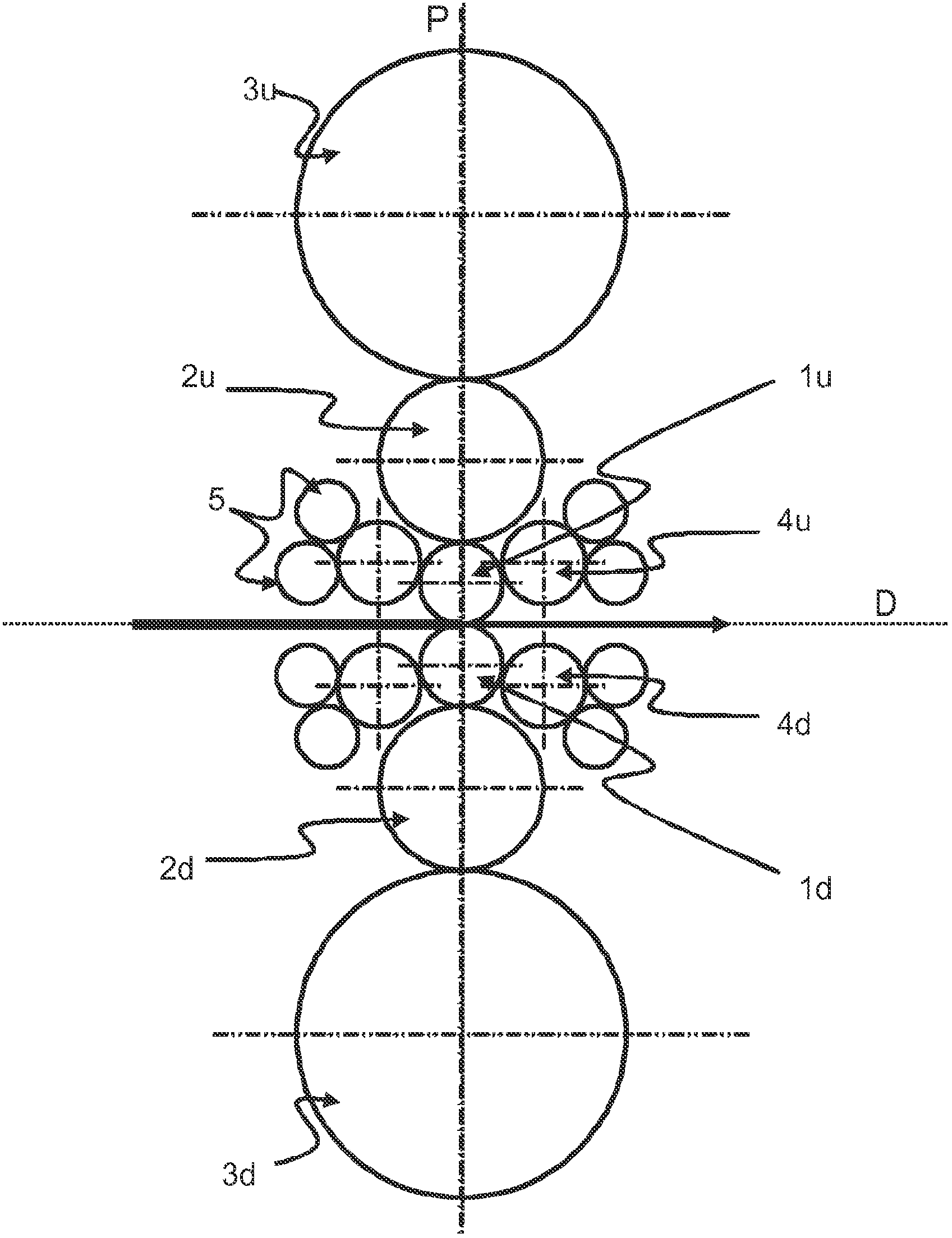
[0055] figure 1 An implementation example of a laterally supported six-roll type rolling stand according to the prior art is shown. Generally, a six-high rolling stand includes two working rolls 1u and 1d with smaller diameters, which are the upper working roll 1u located above the running plane D of the strip to be rolled, and the upper work roll 1u located above the strip to be rolled. The lower work roll 1d below the traveling plane D is moved. The strip to be rolled travels between two work rolls lu, ld supported vertically by a pair of intermediate rolls 2u, 2d, driven in particular by friction, which are themselves pressed against A pair of backup rolls 3u, 3d resting on the pair of intermediate rolls 2u, 2d is vertically supported. The work rolls 1u, 1d have a longitudinal axis of rotation in a plane substantially perpendicular to the plane of travel of the strip, commonly referred to as the clamping plane P. In the case of lateral support, each work roll is not only...


PUM


Abstract

The present invention relates to a roll stand, including two working rollers (1) capable of surrounding a strip to be rolled, two intermediate rollers (2), two bearing rollers (3), and at least one side bearing member (7) capable of laterally supporting said working roller (1); the invention also relates to a method for operating a roll stand, said roll stand being characterized in that at least one camber block (9) for cambering said intermediate rollers (2) is capable of vertical movement relative to the posts (6) of the roll stand and of supporting said side bearing member (7).

Description

technical field [0001] The invention relates to a rolling stand which can be equipped on a rolling plant according to the preambles of claims 1 to 15 above. [0002] The invention relates in particular to the field of rolling metal strips, in particular special steels such as stainless steel, by means of a rolling plant which usually comprises at least one rolling stand. More particularly, the invention relates to the rolling stands of said plant, used for rolling any type of metal, in particular for rolling stainless steel, and methods of operation thereof. Background technique [0003] Typically, a rolling stand is equipped with two vertically superimposed work rolls, each of which has a longitudinal axis of rotation parallel to the plane of travel of the metal strip and positioned between said work rolls and the strip. In the same clamping plane where the direction of travel between them is substantially perpendicular. During rolling, the work rolls are usually pressed ...

Claims


Application Information

Patent Timeline
Patent Type & Authority Applications(China)
IPC IPC(8): B21B13/14
CPCB21B13/145B21B29/00B21B13/14
Inventor 伯纳德·罗西尼厄伊夫·吉约弗朗西斯·沙雷
Owner CLECIM SAS
Why Eureka
Try Eureka