Laundry dryer

A technology for drying racks and hangers, applied in the field of drying racks, can solve problems such as waist pain and discomfort

Inactive Publication Date: 2012-11-14
スビンホームアートカンパニーリミテッド
View PDF4 Cites 12 Cited by
  • Summary
  • Abstract
  • Description
  • Claims
  • Application Information

AI Technical Summary

Problems solved by technology

During this process, in order to hang the clothes in the laundry basket placed on the ground on the clothes rack 10, it is necessary to repeatedly bend and straighten the waist, causing pain and discomfort in the waist

Method used


Image

  • Laundry dryer
  • Laundry dryer
  • Laundry dryer

Examples


Embodiment Construction

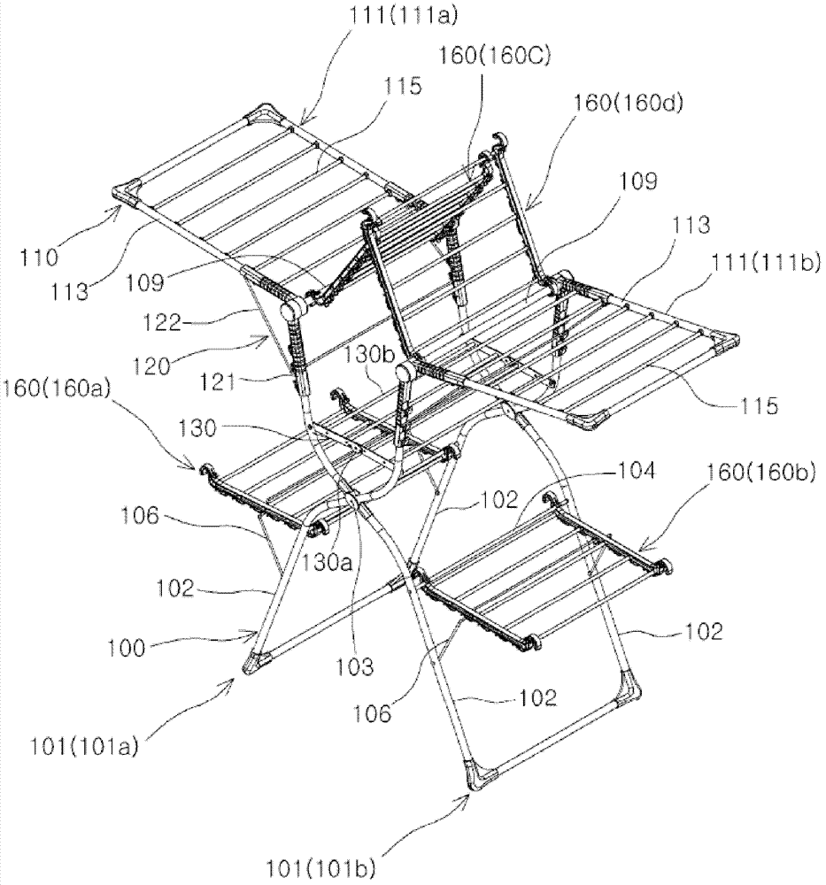
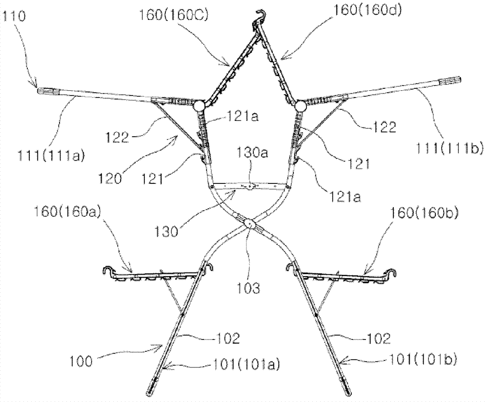
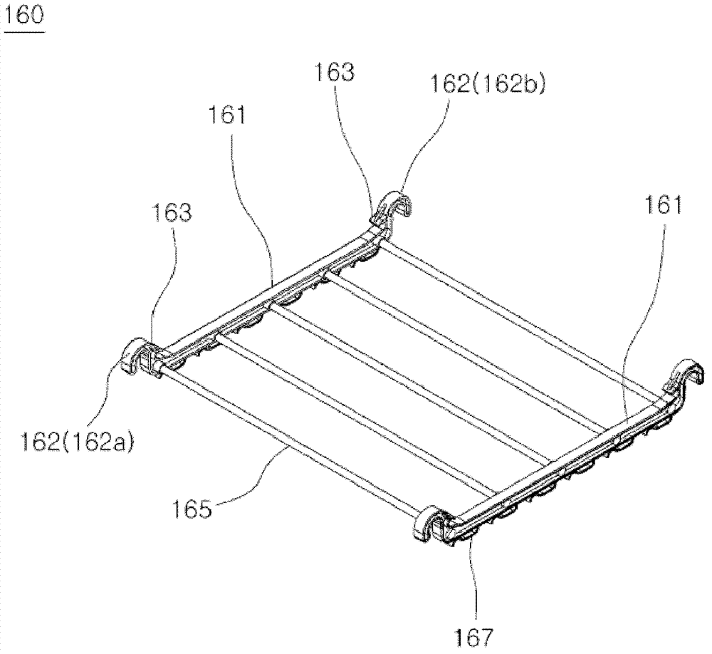
[0070] Figure 1 to Figure 9 It is an embodiment of the clothes drying rack related to the present invention. An embodiment of the clothes drying rack involved in the present invention includes: a supporting unit 100 ; a hanging unit 110 ; an angle adjusting unit 120 ; a bracket 130 ; and an auxiliary hanger 160 .

[0071] The support unit 100 has a pair of legs 101 that intersect each other and are rotatably coupled at an intersecting portion 103 . That is, the support unit 100 has a first leg 101 a and a second leg 101 b that intersect each other and are rotatably coupled at an intersecting portion 103 .

[0072] Here, the leg 101 has a pair of support frames 102 , an auxiliary hanger 104 , an auxiliary support member 106 , and a support rod 109 . The pair of support frames 102 are formed at a predetermined distance from each other in the front and rear. The support rod 109 is used to connect the upper ends of the pair of support frames 102 formed front and rear. In orde...


PUM


Abstract

The present invention relates to a laundry dryer, and more particularly, to a laundry dryer which includes a support for hanging a laundry basket provided to hang laundry without having to bend the body. The laundry dryer includes a support unit, a hanger unit, an angle adjustment unit, and a support. The support unit includes a pair of legs crossing each other and rotatably coupled to each other at a crossing part. The hanger unit hangs the laundry and includes a pair of hangers rotatably coupled to an upper end of each of the legs. The angle adjustment unit supports the hangers to adjust a rotation angle. The support is disposed between the legs above the crossing part. According to the present invention, the laundry dryer including the support between the legs crossing each other may be provided to hang the laundry basket on the support; thus, a user may hang the laundry on the laundry dryer by taking the laundry out of the laundry basket without having to bend the body. Therefore, it may be unnecessary to repeatedly perform bending and straightening of the body.

Description

technical field [0001] The present invention relates to a clothes drying rack, more particularly, to a clothes drying rack with a bracket for placing laundry baskets so that clothes can be hung without bending over. Background technique [0002] Recently drying clothes utilizes the clothes hanger that indoor or balcony is provided with to realize, and existing clothes hanger, such as Figure 15 Shown, substantially by a pair of supporting legs 11 and a pair of hanger 12 that rotates on above-mentioned supporting leg 11 and can dry clothes and constitute, the bottom of supporting leg 11 is supported by ground respectively, and upper end is connected with hanger 12 hinges. Also, the central portions of the pair of legs 11 are connected by a connecting member 13 so as to limit the maximum rotation angle at which the legs 11 are opened to both sides. The connecting member 13 is formed such that its central portions are connected by a hinge so that half areas thereof can rotate r...

Claims


Application Information

Patent Timeline
Patent Type & Authority Applications(China)
IPC IPC(8): D06F57/04D06F57/02D06F57/00
CPCD06F57/10
Inventor 吴修彬
Owner スビンホームアートカンパニーリミテッド
Why Eureka
Try Eureka