

Novel debugging clamp plate mechanism
A pressure plate, a new type of technology, applied in the direction of metal processing machinery parts, clamping, support, etc., can solve the problems of inconvenient adjustment and use of the pressure plate, long auxiliary time for adjustment, passive and other problems, achieve good integration effect, improve passive problems, Easy-to-use effects
Inactive Publication Date: 2012-11-21
唐向平
View PDF0 Cites 0 Cited by
- Summary
- Abstract
- Description
- Claims
- Application Information
AI Technical Summary
Problems solved by technology
[0002] The pressure plate is a machine tool accessory used to fix workpieces, molds, tools, etc. in mechanical manufacturing. At present, the pressure plates used in mechanical manufacturing are all discrete components. In this way, it is inconvenient to adjust the pressure plate with discrete components, and the auxiliary time for adjustment is long. , it is easy to bring about passivity in work
Method used
View moreImage
Smart ImageViewing Examples

Examples
Embodiment Construction
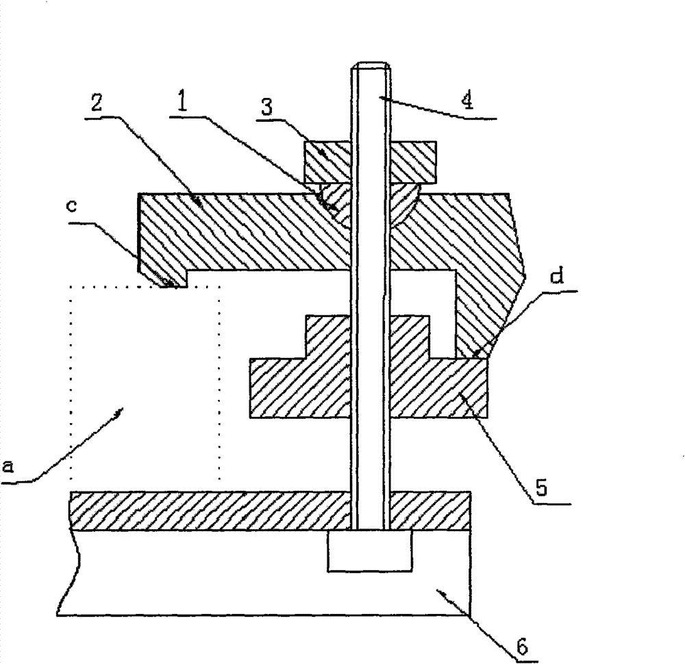
[0009] It consists of a spherical washer 1, an L-shaped pressure plate 2, a positioning nut 3, a T-shaped bolt 4, a stepped nut 5 and a worktable 6; it inserts the T-shaped head of the T-shaped bolt 4 into the T-shaped slot of the machine table 6 , according to the height of the workpiece a, adjust the stepped nut 5 against the end d of the L-shaped pressure plate 2, tighten the positioning nut 3 and clamp the workpiece a on the workbench 6 through the spherical washer 1 and the end c of the L-shaped pressure plate 2 Top: Tighten or loosen the adjustment positioning nut 3 and the step nut 5 to adjust the height of the L-shaped pressure plate clamping and fixing the workpiece a.
Login to View More PUM
 Abstract
The invention discloses a novel debugging clamp plate mechanism which consists of a spherical washer, an L-shaped clamp plate, a positioning nut, a T-shaped bolt, a step nut and a workbench. The T-shaped head part of the T-shaped bolt is inserted into a T-shaped groove of the workbench of a machine tool; the step nut is adjusted to prop against the end part d of the L-shaped clamp plate according to the height of a workpiece a; then the positioning nut is screwed down, and the workpiece a can be clamped on the workbench through the spherical washer and the end part c of the L-shaped clamp plate; and the height of the workpiece a clamped and fixed by the L-shaped clamp plate can be adjusted by screwing down or screwing off the positioning nut and the step nut.
Description
technical field [0001] The invention relates to a debugging press plate mechanism, in particular to a novel debugging press plate mechanism, which belongs to the technical field of machine tool accessories. Background technique [0002] The pressure plate is a machine tool accessory used to fix workpieces, molds, tools, etc. in mechanical manufacturing. At present, the pressure plates used in mechanical manufacturing are all discrete components. In this way, it is inconvenient to adjust the pressure plate with discrete components, and the auxiliary time for adjustment is long. , it is easy to bring about passivity in work Contents of the invention [0003] The object of the present invention is to provide an integrated debugging structure of the pressing plate, which can improve the passive problem caused by the separate component structure of the current pressing plate, thereby bringing convenience in work. [0004] The technical solution adopted by the present invention...
Claims
Login to View More Application Information
Patent Timeline
 Patent Type & AuthorityApplications(China)
IPC IPC(8): B23Q3/02
Inventor唐向平
Owner唐向平