

Rubber air nozzle structure
A technology of rubber gas and gas nozzles, applied in the direction of control valves, functional valve types, engine components, etc., can solve the problems of passive use and gas outflow, etc., and achieve the effect of simple structure and good use effect
Inactive Publication Date: 2014-01-15
XUZHOU CONTENT TRANSMISSION TECH
View PDF0 Cites 1 Cited by
- Summary
- Abstract
- Description
- Claims
- Application Information
AI Technical Summary
Problems solved by technology
[0002] At present, items such as swimming rings, rubber boats, and inflatable toys are mostly equipped with air nozzles. However, most of the current air nozzles are tubular structures with covers. Using such air nozzles, when blowing air into the air nozzles , usually you need to block the gas nozzle with your fingers after each breath, otherwise, the gas that has been blown in will easily flow out of the gas nozzle, which will easily lead to passive use
Method used
View moreImage
Smart ImageViewing Examples

Examples
Embodiment Construction
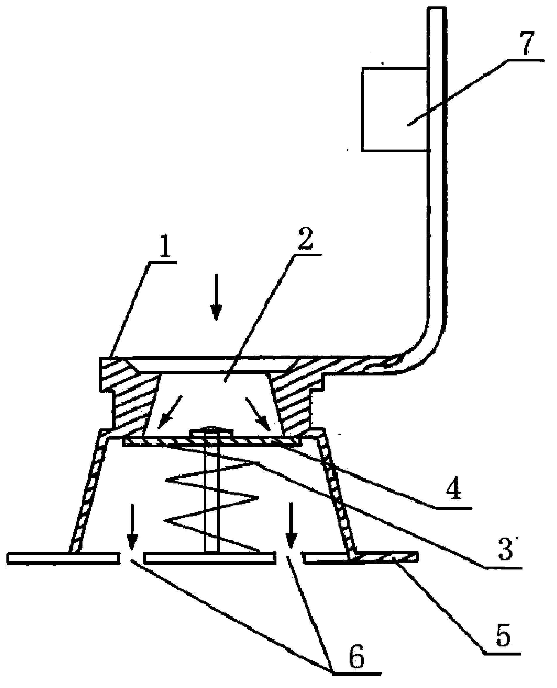
[0008] figure 1 Among them, it consists of air nozzle (1), flushing and exhaust pipe (2), rubber column (3), single valve plate (4), base (5), air hole (6) and cover (7), among which, It is provided with a single valve plate (4) made of rubber on the rubber column (3) of the base (5) under the hollow inflation and exhaust pipe (2) of the valve (1), and a vent hole is provided on the base (5) (6).
Login to View More PUM
 Abstract
Disclosed is a rubber air nozzle structure. A rubber one-way valve block is arranged on a rubber column of a base below a hollow inflation and deflation pipe of an air nozzle. The base is provided with a ventilation hole. Pressure gas blown into an inflation and deflation hole of the air nozzle can jack the edge of the one-way valve block open in the direction indicated in the chart 1 so as to enter the ventilation hole of the base; under the action of the elastic force action of the rubber column, the one-way valve block can block the lower portion of the inflation and deflation hole so that the gas in the ventilation hole cannot be exhausted out of the air nozzle freely; the gas in the ventilation hole can be exhausted out of the air nozzle by jacking and pressing the one-way valve block by articles such as toothpicks, and a cover can cover the inflation and deflation pipe. The rubber air nozzle structure has the advantages that the rubber one-way valve block is arranged on the rubber column of the base below the hollow inflation and deflation pipe of the air nozzle, so that the current passivity problem that the air nozzle needs to be blocked by a hand every time after air is blown to the air nozzle can be solved, the structure is simple and the use effect is good.
Description
technical field [0001] The invention relates to a gas nozzle structure, in particular to a rubber gas nozzle structure, and belongs to the technical field of gas nozzles. Background technique [0002] At present, items such as swimming rings, rubber boats, and inflatable toys are mostly equipped with air nozzles. However, most of the current air nozzles are tubular structures with covers. Using such air nozzles, when blowing air into the air nozzles , Usually after each breath is blown, the gas nozzle needs to be blocked with fingers, otherwise, the gas that has been blown in will easily flow out of the gas nozzle, which will easily lead to passive use. Contents of the invention [0003] The purpose of the present invention is to provide a rubber valve structure, which can improve the above-mentioned defects in the existing valve technology, so as to bring convenience in use. [0004] The technical solution adopted by the present invention to solve its technical problems ...
Claims
Login to View More Application Information
Patent Timeline
 IPC IPC(8): F16K15/20
CPCF16K15/205
Inventor藏继民
OwnerXUZHOU CONTENT TRANSMISSION TECH