Quick plug structure for connector

A plug-in structure and connector technology, which is applied in the direction of connection, two-part connection device, parts of the connection device, etc., can solve the problems of low frequency of use, inconvenient installation and connection operation, and low efficiency of disassembly and assembly.

Pending Publication Date: 2019-04-16
JIANGSU LIANHAI COMM
View PDF7 Cites 0 Cited by
  • Summary
  • Abstract
  • Description
  • Claims
  • Application Information

AI Technical Summary

Problems solved by technology

[0002] When the traditional radio frequency connector is installed, the outer conductor is tightened by rotating the screw sleeve to achieve mechanical connection. The installation and connection operation is inconvenient and the disassembly efficiency is low. At this stage, the frequency band used by 5G communication in the telecommunications field has been developed and extended to 6GHz, while the traditional radio frequency connector cannot be used at the same time. Meet the use requirements of small size, high integration, moderate power, high frequency band and low intermodulation. Although some products can use the frequency band to meet the use requirements, there are application defects in intermodulation and power indicators. Some products can meet the use requirements but the intermodulation indicators Its frequency of use is relatively low; for example, 4310, 7 / 16, and N-type connectors in the prior art can meet some requirements, but there are defects in volume and integration. 16mm; small size connectors such as SMA, SMB, etc. have problems of too small power and poor stability of intermodulation indicators; therefore, traditional connectors cannot meet the requirements of 5G communication

Method used


Image

  • Quick plug structure for connector
  • Quick plug structure for connector
  • Quick plug structure for connector

Examples


Embodiment Construction

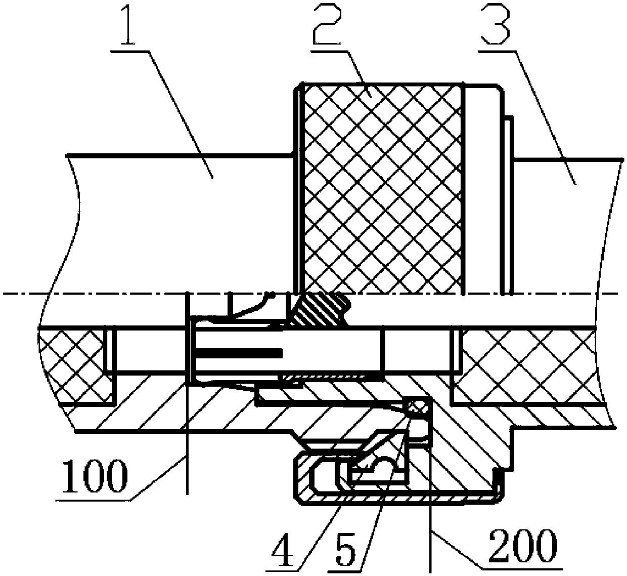
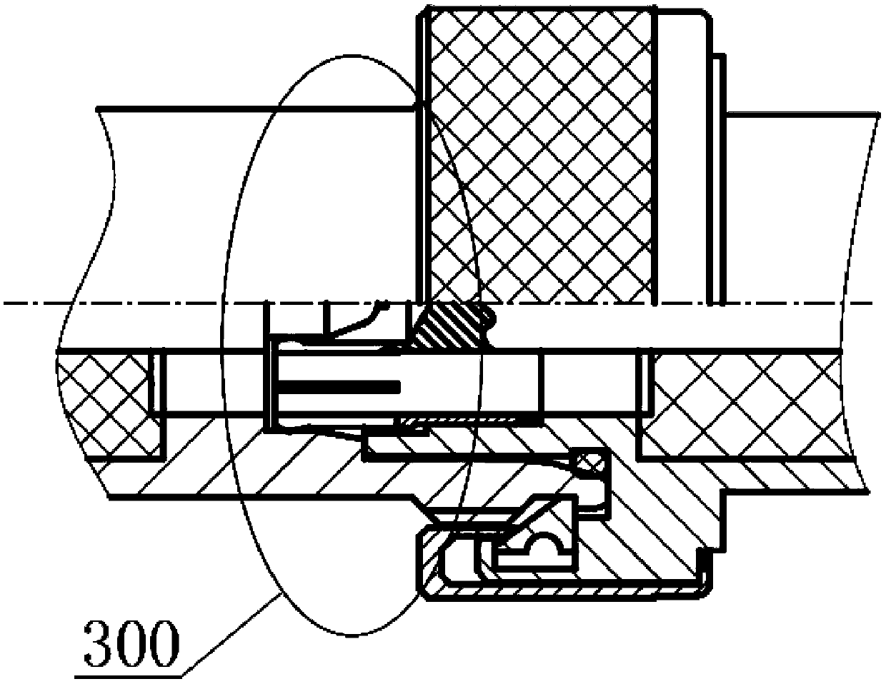
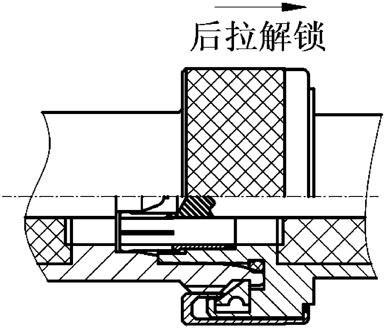
[0021] As shown in the figure, a connector quick-plug structure includes a male connector and a female connector. The outer conductor of the male connector is inserted into the female outer conductor of the female connector for installation and connection, and the outer conductor of the male connector The outer peripheral surface of the conductor 3 is provided with an outwardly protruding limiting boss, and the rear end surface of the female outer conductor 1 cooperates with the limiting boss to limit the position; the outer ring of the front surface of the outer limiting boss of the male outer conductor 3 is set There is a flange extending forward in the axial direction, an annular groove is arranged on the inner surface of the flange, an elastic collar 4 is arranged in the annular groove, the front section of the inner side of the elastic collar 4 is an inner cone surface, and the elastic collar The axial middle part of the outer surface corresponding to the inner cone surfac...


PUM


Abstract

The invention relates to a quick plug structure for a connector. When a male outer conductor is plugged into and matched with a female outer conductor, the rear end of the female outer conductor propsopen an elastic clamping ring, the elastic clamping ring enters a limit clamping slot in the outer circumferential surface of the female outer conductor, a right angle limit surface of the rear end of the elastic clamping ring is in fit with and limited by the limit clamping slot of the female outer conductor limit clamping slot and the rear side surface of a circular groove of the male outer conductor and can not exit; during disassembly, an unlocking sleeve is pulled to move backward along the outer surface of a limit boss, the edge of an annular inner ring props open the elastic clamping ring along an interior conical surface to exit from the limit clamping slot of the female outer conductor, and the female outer conductor can be disassembled after moving forward to exit. The quick plug structure for the connector has the advantages that size is small, weight is light, installation is quick, a connection operation is easy, coaxiality is good, quick plug can be realized, working efficiency is improved, and all the usage frequency band, intermodulation and power indexes respectively meet 5G communication using requirements.

Description

technical field [0001] The invention relates to a connector quick plug-in structure for a C5G radio frequency coaxial connector in the communication field. Background technique [0002] When the traditional radio frequency connector is installed, the outer conductor is tightened by rotating the screw sleeve to achieve mechanical connection. The installation and connection operation is inconvenient and the disassembly efficiency is low. At this stage, the frequency band used by 5G communication in the telecommunications field has been developed and extended to 6GHz, while the traditional radio frequency connector cannot be used at the same time. Meet the use requirements of small size, high integration, moderate power, high frequency band and low intermodulation. Although some products can use the frequency band to meet the use requirements, there are application defects in intermodulation and power indicators. Some products can meet the use requirements but the intermodulatio...

Claims


Application Information

Patent Timeline
Patent Type & Authority Applications(China)
IPC IPC(8): H01R13/02H01R13/627H01R13/633H01R24/00H01R24/40
CPCH01R13/02H01R13/6277H01R13/6335H01R24/00H01R24/40
Inventor 张瑞峰徐晨晨王俊
Owner JIANGSU LIANHAI COMM
Why Eureka
Try Eureka