Power grid reactive power compensation method, device and grid-connected inverter

A compensation device and compensation method technology, applied in reactive power compensation, reactive power adjustment/elimination/compensation, output power conversion devices, etc., can solve the problem of large switching loss and inductance loss, unable to realize reactive power compensation, and difficult to achieve Soft switching and other issues to achieve the effect of reducing switching loss and inductance loss

Active Publication Date: 2015-09-09
HUAWEI DIGITAL POWER TECH CO LTD
View PDF4 Cites 0 Cited by
  • Summary
  • Abstract
  • Description
  • Claims
  • Application Information

AI Technical Summary

Problems solved by technology

Among them, when the bipolar modulation method is used to realize reactive power compensation, there is no special requirement for the current grid voltage value, but the switching loss and inductance loss are relatively large compared with the unipolar modulation method; while the unipolar modulation method is used to realize reactive power compensation , it can have small switching loss and inductance loss, but it is difficult to achieve soft switching when the grid voltage is low (such as near zero crossing of the grid voltage), so that reactive power compensation cannot be realized

Method used


Image

  • Power grid reactive power compensation method, device and grid-connected inverter
  • Power grid reactive power compensation method, device and grid-connected inverter
  • Power grid reactive power compensation method, device and grid-connected inverter

Examples


Embodiment Construction

[0036] The following will clearly and completely describe the technical solutions in the embodiments of the present invention with reference to the accompanying drawings in the embodiments of the present invention. Obviously, the described embodiments are only some of the embodiments of the present invention, not all of them. Based on the embodiments of the present invention, all other embodiments obtained by persons of ordinary skill in the art without making creative efforts belong to the protection scope of the present invention.

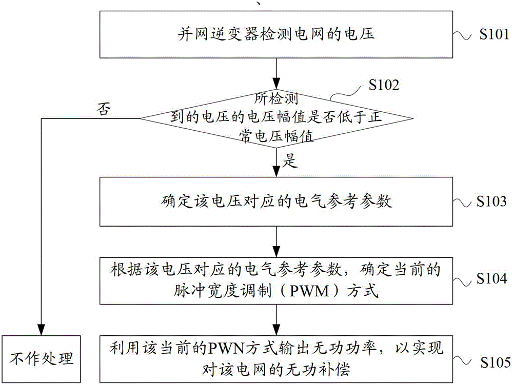
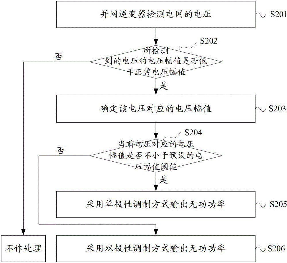
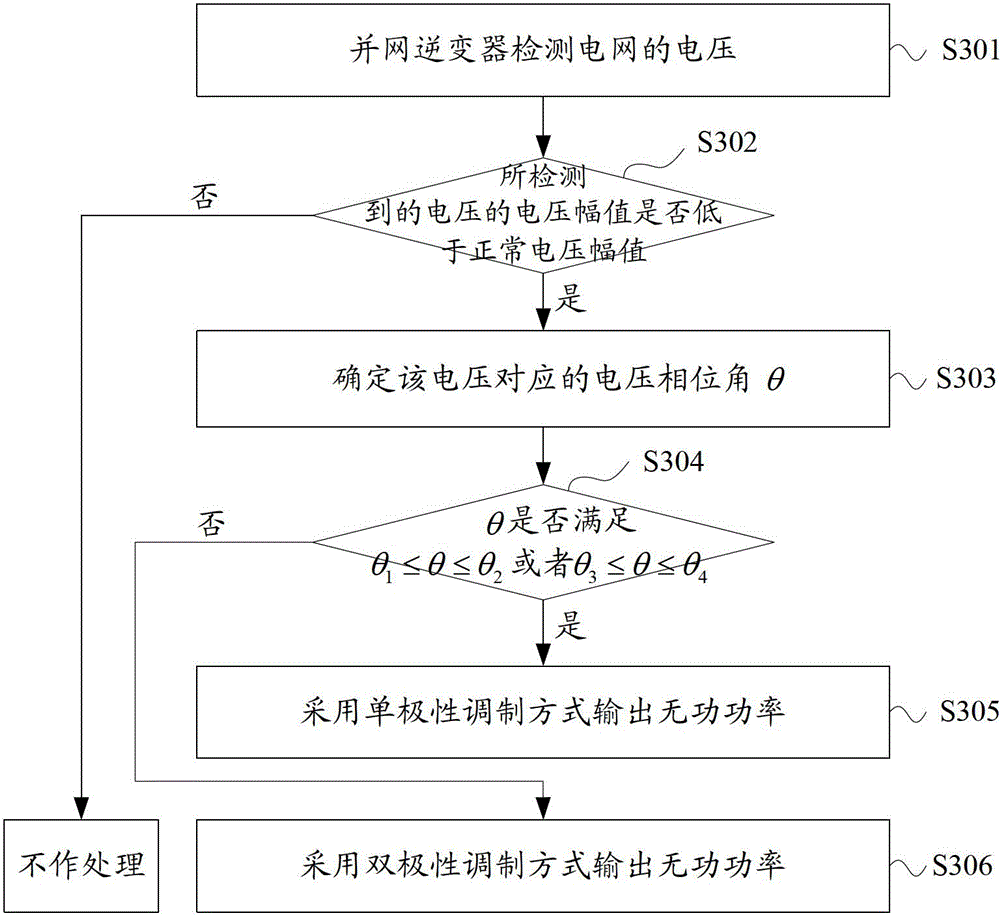
[0037] In order to effectively realize reactive power compensation while reducing switching loss and inductance loss when the grid voltage drops, the invention provides a grid reactive power compensation method, device and grid-connected inverter.

[0038] A method for reactive power compensation of a power grid provided by an embodiment of the present invention is firstly introduced below.

[0039] It should be noted that a grid reactive power c...


PUM


Abstract

The present invention discloses a method for reactive power compensation of power grid, an apparatus for reactive power compensation of power grid and a grid-tied inverter. The method for reactive power compensation of power grid includes: detecting voltage of a power grid; when a voltage magnitude of the detected voltage is lower than a preset normal voltage magnitude, determining an electric reference parameter corresponding to the voltage; determining a current pulse width modulation (PWM) mode according to the electric reference parameter corresponding to the voltage, where the PWM mode includes: a unipolar modulation mode and a bipolar modulation mode; and outputting reactive power by using the current PWM mode, so as to implement reactive power compensation for the power grid. In this solution, the current PWM mode is determined through the electric reference parameter corresponding to the detected voltage at the time of voltage dip of the power grid, so as to effectively combine the unipolar modulation mode and the bipolar modulation mode in one current period; then at the time of voltage dip of the power grid, effective reactive power compensation is performed on the power grid, and meanwhile the switching loss and the inductance loss are reduced.

Description

technical field [0001] The invention relates to the field of electrical technology, in particular to a grid reactive power compensation method, device and grid-connected inverter. Background technique [0002] As an environmentally friendly and renewable new energy, solar energy is increasingly favored by people. Among them, the conversion of solar energy into electrical energy has received particular attention. In order to convert the direct current generated by the solar panels into alternating current for feeding into the grid, a solar grid-connected inverter is required. [0003] Among them, when there is a power grid failure due to voltage drop, the solar inverter is required to be able to output reactive power to achieve reactive power compensation, thereby supporting the recovery of the power grid. Among them, the so-called voltage drop specifically refers to the decrease of the voltage amplitude of the power grid; the so-called reactive power refers to the electric...

Claims


Application Information

Patent Timeline
Patent Type & Authority Patents(China)
IPC IPC(8): H02J3/18H02M7/48
CPCH02M7/48H02M7/5387H02J3/18H02M7/538H02M1/126H02M1/42Y02B70/1491H02M2001/0054Y02B70/12H02M1/0054Y02B70/10Y02E40/30
Inventor 张彦忠高拥兵郭新
Owner HUAWEI DIGITAL POWER TECH CO LTD
Why Eureka
Try Eureka