
Floatation device for solar panels

A technology of solar panels, equipment, applied in the field of frame, base or support

Inactive Publication Date: 2012-11-21
C & L PASTORAL COMPANY
View PDF4 Cites 18 Cited by
  • Summary
  • Abstract
  • Description
  • Claims
  • Application Information

AI Technical Summary

Problems solved by technology

However, a relatively bulky or complex mechanism is required to allow the ground-based solar panel array to be rotated as a whole through different rotation angles
Applicant has identified that ground-based solar panel arrays may have significant tracking issues due to the complexity required

Method used


Image

  • Floatation device for solar panels
  • Floatation device for solar panels
  • Floatation device for solar panels

Examples


Embodiment Construction

[0063] The following modes are described below, given by way of example only, to provide a more precise understanding of the preferred embodiment or the subject matter of each embodiment.

[0064] In the drawings, which are incorporated to illustrate features of the example embodiments, like reference numerals refer to like parts throughout the views.

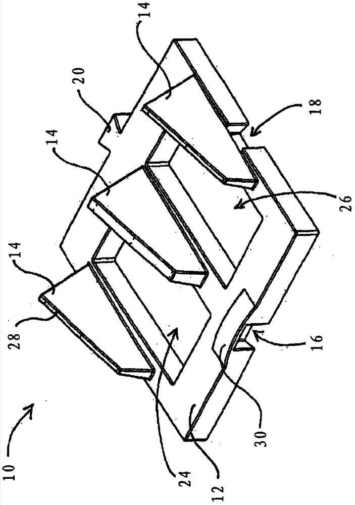
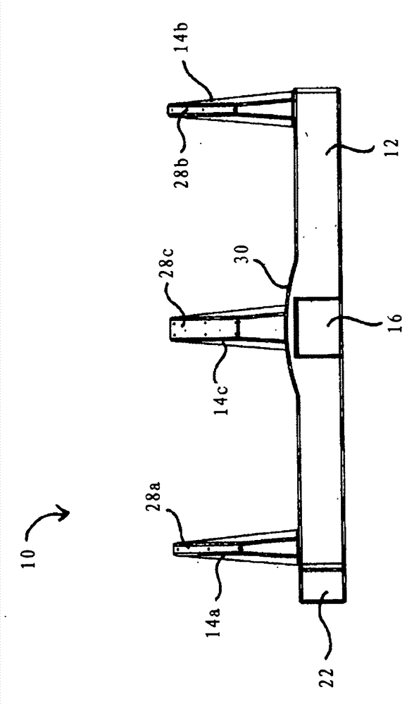
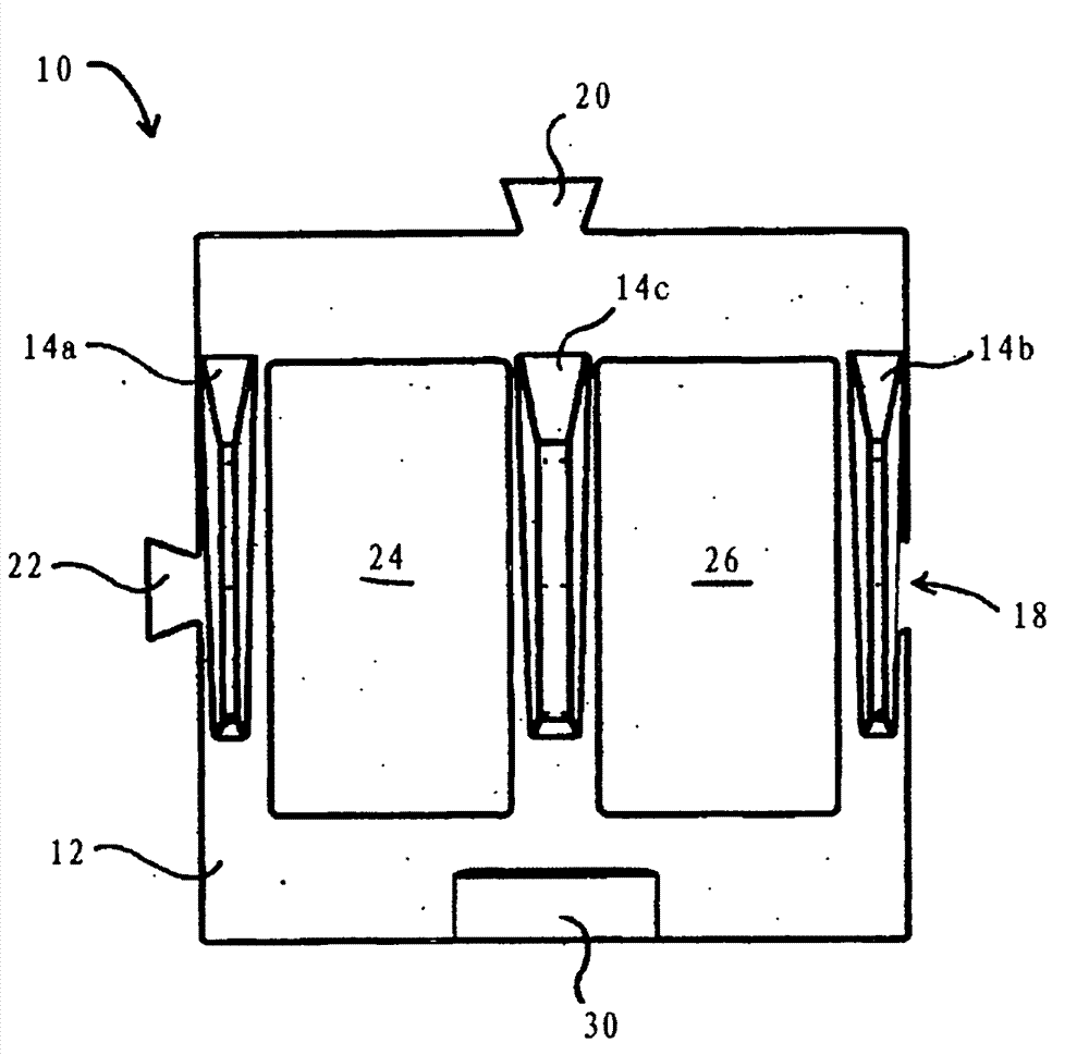
[0065] refer to figure 1 , shows a floating device 10 for supporting at least one photovoltaic solar panel (not shown) above a body of water. The floatation device 10 includes a base 12 capable of floating on a body of water. The substrate can be partially or fully submerged as long as the supporting photovoltaic solar panels are above the surface of the body of water. At least one support 14 is also provided for angularly (ie pitch angle) positioning of at least one photovoltaic solar panel with respect to the base 12 . At least one support 14 is used to hold or mount at least one photovoltaic solar panel at a desired pitch...


PUM


Abstract

There is provided a floatation device for supporting at least one photovoltaic solar panel above a body of water. Preferably, the floatation device includes a base that is able to float on or in the body of water, and at least one support to position the at least one photovoltaic solar panel at an angle to the base. At least one coupling member is used to couple the floatation device to an adjacent floatation device. In various embodiments an array of floatation devices holding solar panels can be constructed that can be rotated on the body of water to relatively easily track the motion of the sun across the sky during the day. The pitch angle of solar panels can be fixed or varied. Optionally, the base includes at least one opening.

Description

technical field [0001] The present invention generally relates to frames, mounts or supports for photovoltaic solar panels. More specifically, the present invention relates to flotation devices that may be used as frames, bases or supports to enable solar panels to float on or over bodies of water. Background technique [0002] Photovoltaic solar panels are well known and convert electromagnetic radiation from the sun into electrical current. This renewable energy source continues to attract high levels of research and commercial interest. [0003] In use, photovoltaic solar panels are typically mounted on a support frame. Traditional frames support the solar panels above the ground and at an angle (ie, dip) to an axis parallel to the ground. This generally means that the solar panel array has a fixed rotational orientation (ie rotation angle) about an axis perpendicular to the ground. To improve efficiency, it would first be desirable to be able to change the angle of r...

Claims


Application Information

Patent Timeline
Patent Type & Authority Applications(China)
IPC IPC(8): F24J2/00B63B35/34B63B38/00H01L31/04
CPCF24J2/541F24J2/5237B63B35/44B63B35/00Y02E10/50B63B2035/4453H01L31/0422Y02E10/47B63B39/03F24J2/5267H02S20/00F24S2025/6007F24S25/11F24S30/425F24S20/70
Inventor 索伦·伊德·吕诺厄伊曼纽尔·希勒尔·苏迈尔
Owner C & L PASTORAL COMPANY
Learn More