Solar panel racking system

a technology for solar panels and racking, which is applied in the field of solar collection systems, can solve the problems of not supporting photovoltaic panels by their long edges, and achieve the effects of reducing material, labor and system profile, and reducing installation cost and weigh

Inactive Publication Date: 2014-03-04
EIDE KRISTIAN
View PDF47 Cites 47 Cited by
  • Summary
  • Abstract
  • Description
  • Claims
  • Application Information

AI Technical Summary

Benefits of technology

[0007]The solar panel racking system of the invention, particularly useful with photovoltaic panels, overcomes the problems of prior systems and greatly reduces the cost and weight of an installation. It is estimated that the system can save at least 15% on total installation cost, which includes the cost of the photovoltaic panels themselves, and can reduce cost of racking by up to 70%. The racking system greatly reduces material, labor and system profile as compared to previous mounting systems. Special pedestals are secured to a roof at far larger spacings and fewer number than required in previous systems. The pedestals are configured for efficient and dependable flashing for waterproofing the roof. These pedestals, in an assembly according to the invention, can be at least at five foot spacings and preferably about eight foot spacings or greater horizontally (laterally, parallel to the long dimension of the panels typically east-west direction) and about five foot or greater spacings in the perpendicular (typically north-south) direction. This greater spacing is due to the efficient structural framework above.
[0008]In assembly the extruded aluminum components are fitted together quickly with efficient, strong and versatile connections, with the photovoltaic panels retained in a compact array and fully supported along the long sides of each panel, with panel edges fitted into structural east-west oriented channel members. The fittings provide for field adjustment of the height of the uprights, helping accommodate uneven roof surfaces, such as flat roofs.
[0010]It is therefore among the objects of the invention to reduce weight and cost of racking for solar panel mounting, while providing for fast and efficient assembly, reliable roof flashing, fewer roof penetrations and field adjustability of height components. These and other objects, advantages and features of the invention will be apparent from the following description of a preferred embodiment, considered along with the accompanying drawings.

Problems solved by technology

Moreover, this previous use of the structural channels had only the narrow sides of panels supported in the channels, failing to support the photovoltaic panels by their long edges.

Method used


Image

  • Solar panel racking system
  • Solar panel racking system
  • Solar panel racking system

Examples


Embodiment Construction

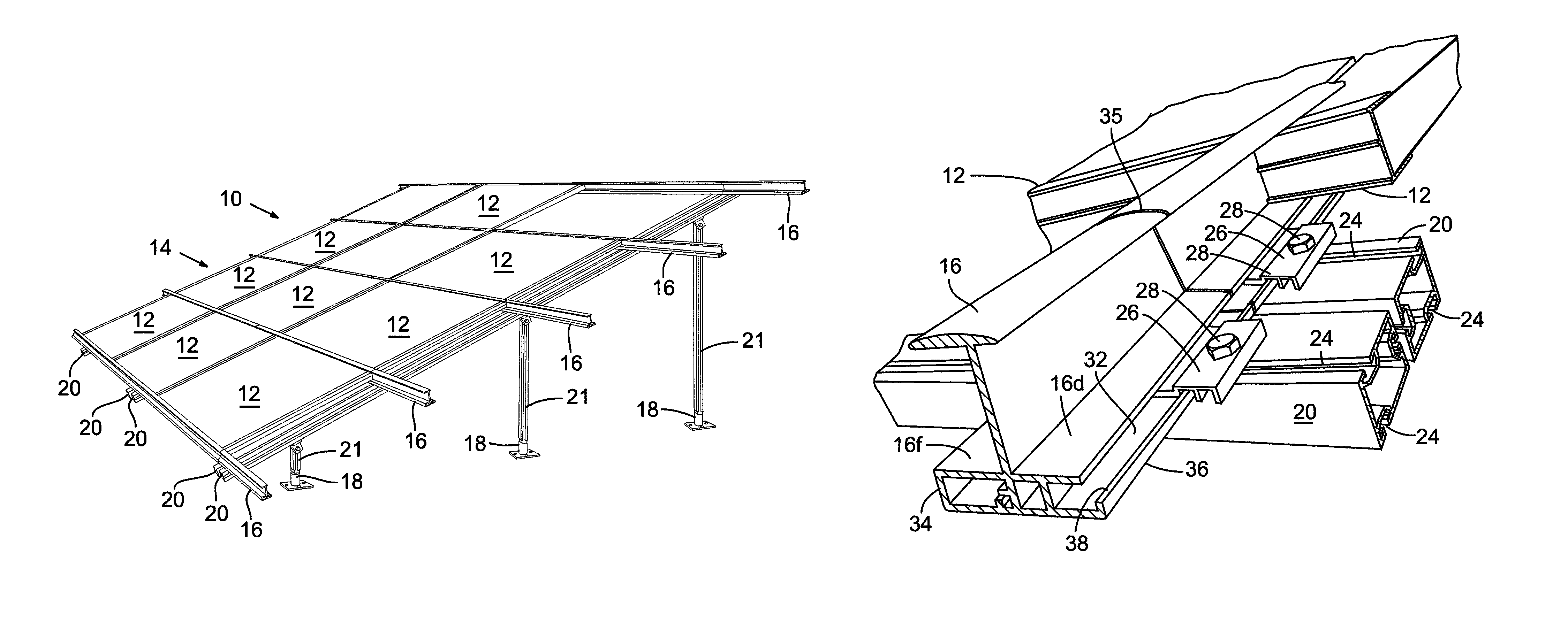
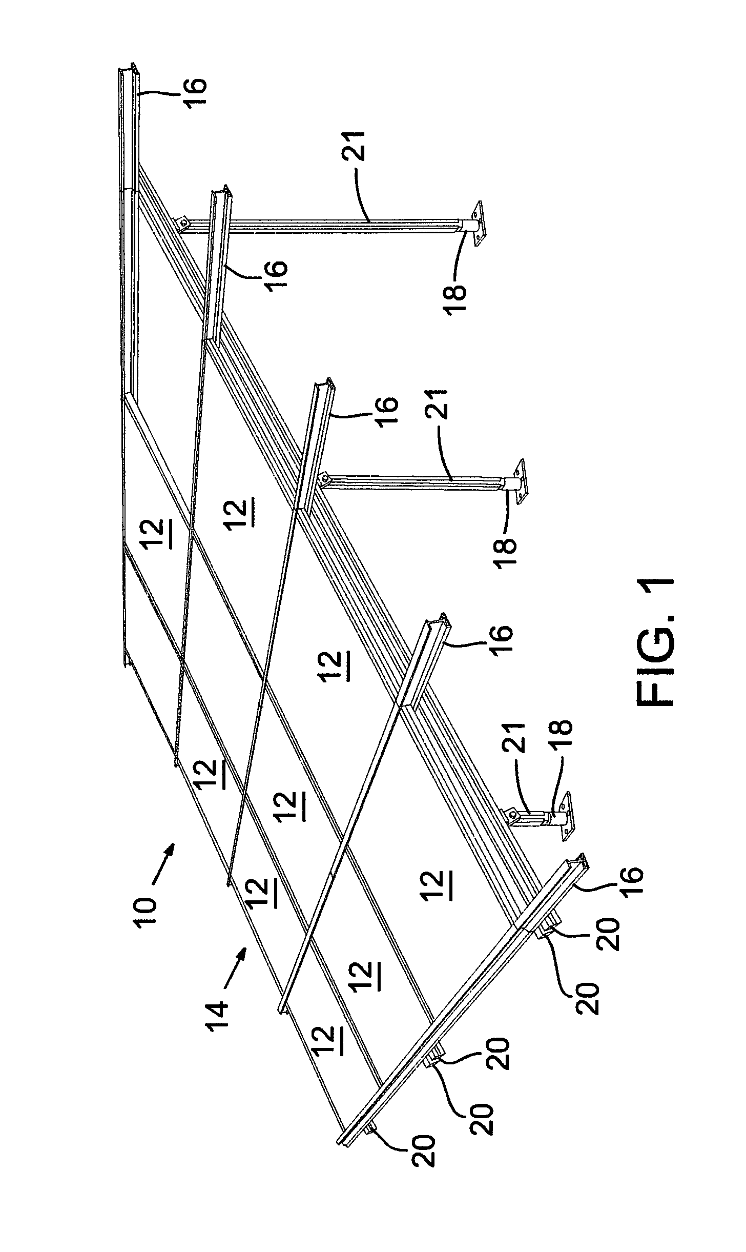
[0025]In the drawings, FIG. 1 shows an example of a tilt-mounted array 10 of rectangular photovoltaic solar collectors 12, in a setup of a racking system 14 comprised primarily of a series of extruded aluminum components in a structural framework. As illustrated, the panels 12 are in a substantially planar grid and arrayed in “landscape” orientation, that is, the long sides of the collector panels in the lateral horizontal direction, sometimes referred to herein as the east-west direction, with the high and low sides of the tilt-up array being north and south, respectively. The use of these directions herein and in the claims is approximate and only for reference, since the north-south directions will be reversed in the southern hemisphere.

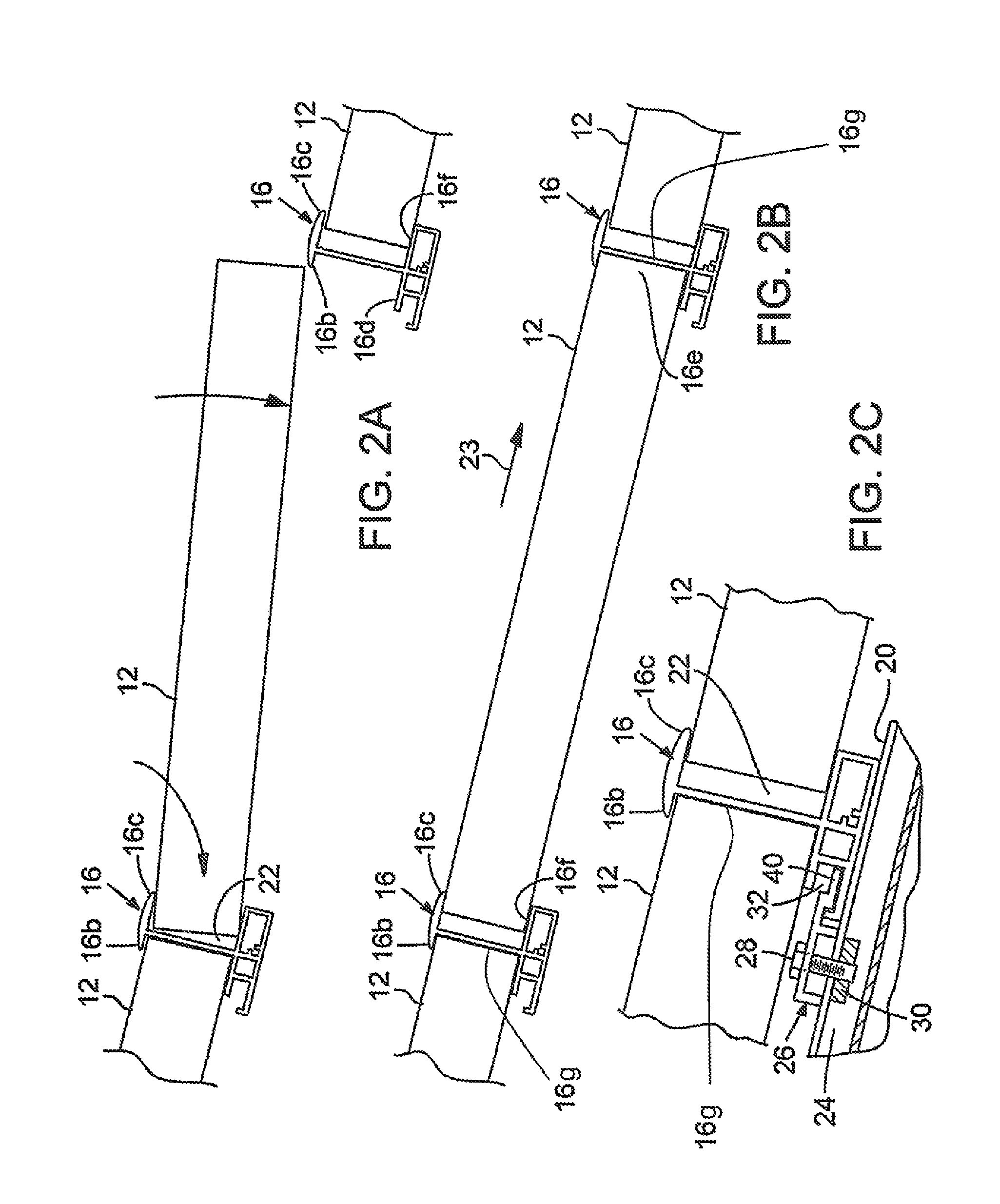
[0026]Importantly, the panels are structurally supported along the length of their long sides, by horizontal structural frame members or channel members 16 which have channels into which the panels are assembled, which can be by sliding them into ...


PUM


Abstract

A racking system for photovoltaic solar panels greatly reduces material, weight, labor and system profile as compared to previous mounting systems. Special pedestals are secured to a roof at far larger spacings and fewer number than required in previous systems. The pedestals are configured for efficient and dependable flashing for waterproofing the roof. In assembly the extruded aluminum components are fitted together quickly with efficient and strong connections, with the photovoltaic panels retained in a compact array and fully supported along the length of each panel. The fittings provide for field adjustment of the height of the uprights, helping accommodate uneven roof surfaces, such as flat roofs.

Description

[0001]This application claims priority from provisional application No. 61 / 400,208, filed Jul. 23, 2010.BACKGROUND OF THE INVENTION[0002]This invention concerns solar collection systems, and particularly a racking or mounting system especially for photovoltaic solar panels, typically roof-mounted but also ground-mounted, in a tilted-up array.[0003]Many different arrangements have been suggested in the literature and used for supporting an array of solar collector panels, either on roof surfaces or ground mounted. Examples are shown in U.S. Pat. Nos. 7,531,741, 4,278,070, 6,105,317 and U.S. Pub. No. 2003 / 0094193. It is known to use aluminum extrusions for support members and joists or beams in a solar panel racking system.[0004]Prior to this invention solar panel racking systems have employed roof-secured pedestals which are difficult to reliably waterproof, and these roof mountings have been positioned as closely as every four feet. Typically, the systems had a very large number of ...

Claims


Application Information

Patent Timeline
Patent Type & Authority Patents(United States)
IPC IPC(8): F24J2/46E04D13/03E04D13/18E04B7/02
CPCE04B1/38E04B7/022H01L31/0484Y02B10/20Y02B10/12H01L31/0422Y02E10/50F24J2/5232F24J2002/5215F24J2/5207Y02E10/47E04D13/031F24J2/46E04B1/58H02S20/24H02S20/00H02S20/30F24S25/35F24S25/12F24S2025/801F24S25/13F24S25/61F24S80/00Y02B10/10E04B7/22E04H12/18
Inventor EIDE, KRISTIAN
Owner EIDE KRISTIAN
Why Eureka
Try Eureka