Meter pointer angle identification method based on image processing

An instrument pointer and image processing technology, which is applied in the field of image processing, can solve problems such as the large error of the instrument pointer frame difference method, and achieve the effects of eliminating detection deviations, intuitive image processing results, and improving performance

Active Publication Date: 2012-11-28
宁波智能装备研究院有限公司
View PDF1 Cites 55 Cited by
  • Summary
  • Abstract
  • Description
  • Claims
  • Application Information

AI Technical Summary

Problems solved by technology

[0006] The purpose of the present invention is to solve the problem that the frame difference method of using the absolute angle method ...

Method used


Image

  • Meter pointer angle identification method based on image processing
  • Meter pointer angle identification method based on image processing
  • Meter pointer angle identification method based on image processing

Examples


specific Embodiment approach 1

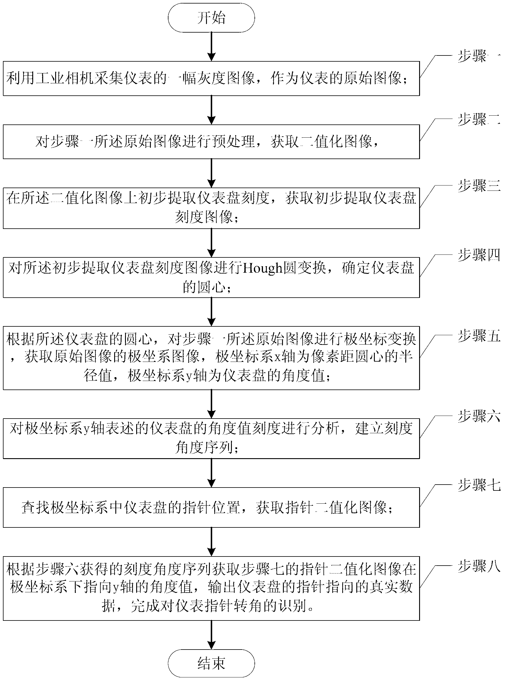
[0046] Specific implementation mode one: the following combination Figure 1 to Figure 23 Describe this embodiment, the image processing-based instrument pointer rotation angle recognition method described in this embodiment, the method includes the following steps:

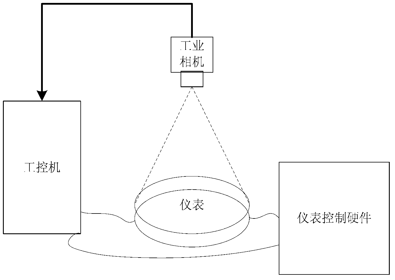
[0047] Step 1. Use an industrial camera to collect a grayscale image of the meter as the original image of the meter; Figure 8 shown.

[0048] Step 2. Preprocessing the original image described in step 1 to obtain a binarized image, such as Figure 9 shown.

[0049] Step 3, initially extracting the scale of the instrument panel on the binarized image, and obtaining an image of the scale of the initially extracted instrument panel; as Figure 10 to Figure 13 shown.

[0050] Step 4. Carry out Hough circle transformation to the initially extracted instrument panel scale image to determine the center of the instrument panel;

[0051] Step 5. According to the center of the instrument panel, the original image de...

specific Embodiment approach 2

[0057] Specific implementation mode 2: This implementation mode further explains the implementation mode 1. The process of preprocessing in step 2 and obtaining a binarized image is as follows: see Figure 10 to Figure 13 .

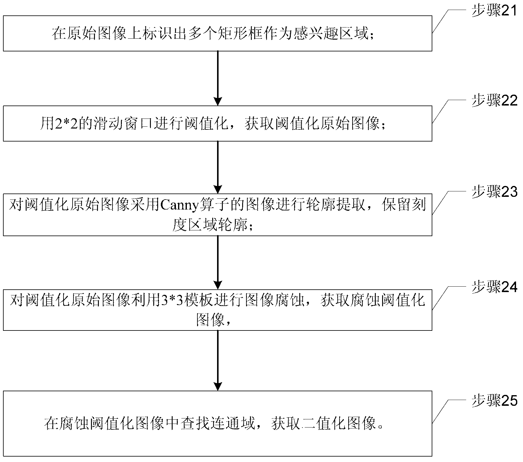
[0058] Step 21, identify a plurality of rectangular frames as regions of interest on the original image;

[0059] Step 22, thresholding with a 2*2 sliding window to obtain the thresholded original image;

[0060] Step 23, extract the outline of the thresholded original image using the Canny operator, and retain the outline of the scale area;

[0061] Step 24: Perform image corrosion on the thresholded original image using a 3*3 template to obtain a corroded thresholded image,

[0062] The 3*3 template traverses the thresholded original image, and if a pixel contains a pixel in the 3*3 region, the pixel is retained; otherwise, the pixel is removed;

[0063] Step 25. Search for connected domains in the erosion-thresholded image to obtain a binarized imag...

specific Embodiment approach 3

[0065] Specific implementation mode three: this implementation mode further explains implementation mode one or two, and the process of initially determining the center of the instrument panel in step four is:

[0066] Step 41, perform Hough circle transformation on the initially extracted instrument panel scale image, and extract a circle that meets the constraint condition, the constraint condition is: the circle contains at least a continuous 180° arc in the image;

[0067] Step 42, judging whether there is a circle meeting the constraints,

[0068] If the judgment result is yes, execute step 43; if the judgment result is no, then reduce the resolution of the initially extracted instrument panel scale image, and then return to execute step 41;

[0069] Step 43. Based on the Hough transformed circle, search for connected domains in the binarized image to obtain an accurate scale image of the instrument panel, and search for connected domains in the binarized image to obtain ...


PUM


Abstract

The invention discloses a meter pointer angle identification method based on image processing, belonging to the field of image processing and solving the problem of large frame difference errors when a meter pointer is detected by adopting an absolute angle method. The meter pointer corner identification method comprises the following steps of: 1, acquiring a gray level image of a meter as an original image; 2, preprocessing to obtain a binarization image; 3, obtaining a preliminarily extracted meter panel scale image; 4, carrying out Hough circle transformation and determining a circle center of a meter panel; 5, according to the circle center of the meter panel, carrying out polar coordinate transformation on the original image to obtain a polar coordinate system image; 6, analyzing an angle value scale of the y axis of a polar coordinate system and establishing a scale angle sequence; 7, searching the position of a pointer in the polar coordinate system to obtain a pointer binarization image; and 8, obtaining an angle value of the pointer binarization image towards the y axis under the polar coordinate system according to the scale angle sequence obtained in the step 6, outputting actual data of pointing of the pointer of the meter panel, and finally identifying the angle of the meter pointer.

Description

technical field [0001] The invention relates to an image processing-based method for recognizing the rotation angle of an instrument pointer, belonging to the field of image processing. Background technique [0002] The use of image processing in the field of industrial inspection is gradually increasing, and the instrument panel inspection based on image processing can largely replace the inspection of instruments by humans. Meter detection mainly refers to the detection of the direction of the pointer, to detect whether the pointer output by the test meter is accurate under a given input signal. [0003] At present, the instrument pointer detection mainly uses the method of absolute angle, mainly adopts the frame difference method, that is, collects two images of different corners of the pointer, and then subtracts them, because only the position of the pointer changes, and only two images will be left after the subtraction. image of a pointer and then process it to figur...

Claims


Application Information

Patent Timeline
IPC IPC(8): G06K9/00G06K9/38
Inventor 钟贤德潘惠惠高会军于金泳
Owner 宁波智能装备研究院有限公司
Why Eureka
Try Eureka