Drilling system and method of operating a drilling system

A technology of drill string and drill floor, which is applied in the field of drilling system with standpipe, and can solve problems such as the inoperability of the steering gear and the maintenance of fluid pressure

Inactive Publication Date: 2015-04-22
MANAGED PRESSURE OPERATIONS PTE
View PDF12 Cites 1 Cited by
  • Summary
  • Abstract
  • Description
  • Claims
  • Application Information

AI Technical Summary

Problems solved by technology

But the diverter cannot operate to maintain fluid pressure in the riser annulus while the drill string is rotating

Method used


Image

  • Drilling system and method of operating a drilling system
  • Drilling system and method of operating a drilling system
  • Drilling system and method of operating a drilling system

Examples


Embodiment Construction

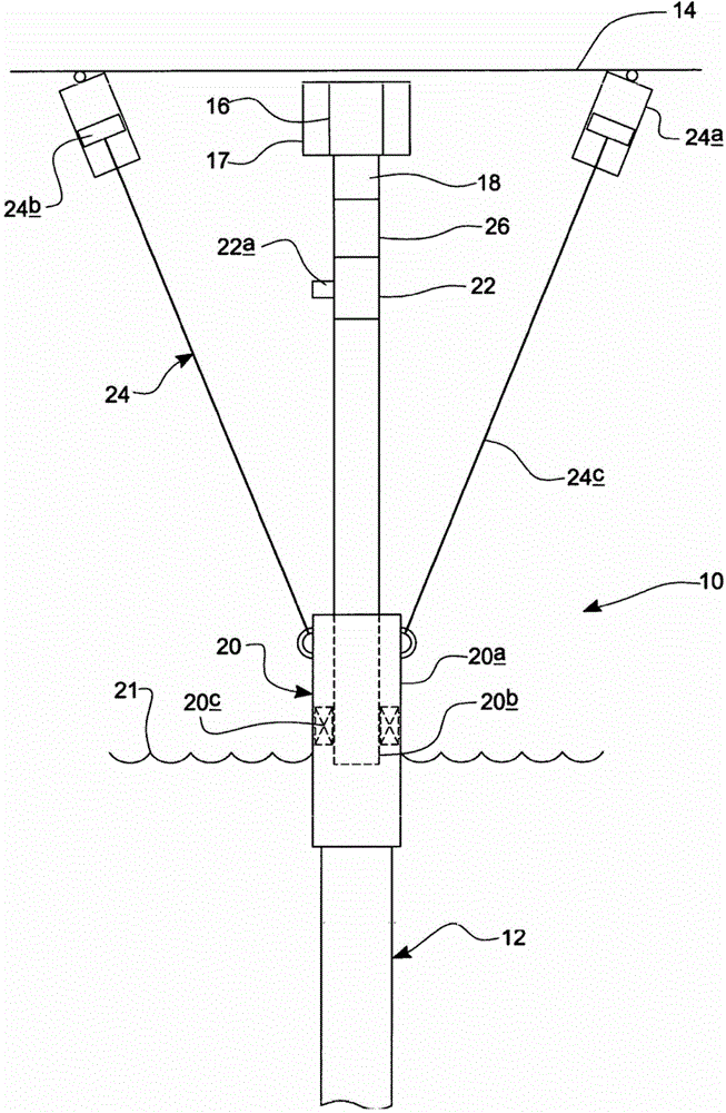
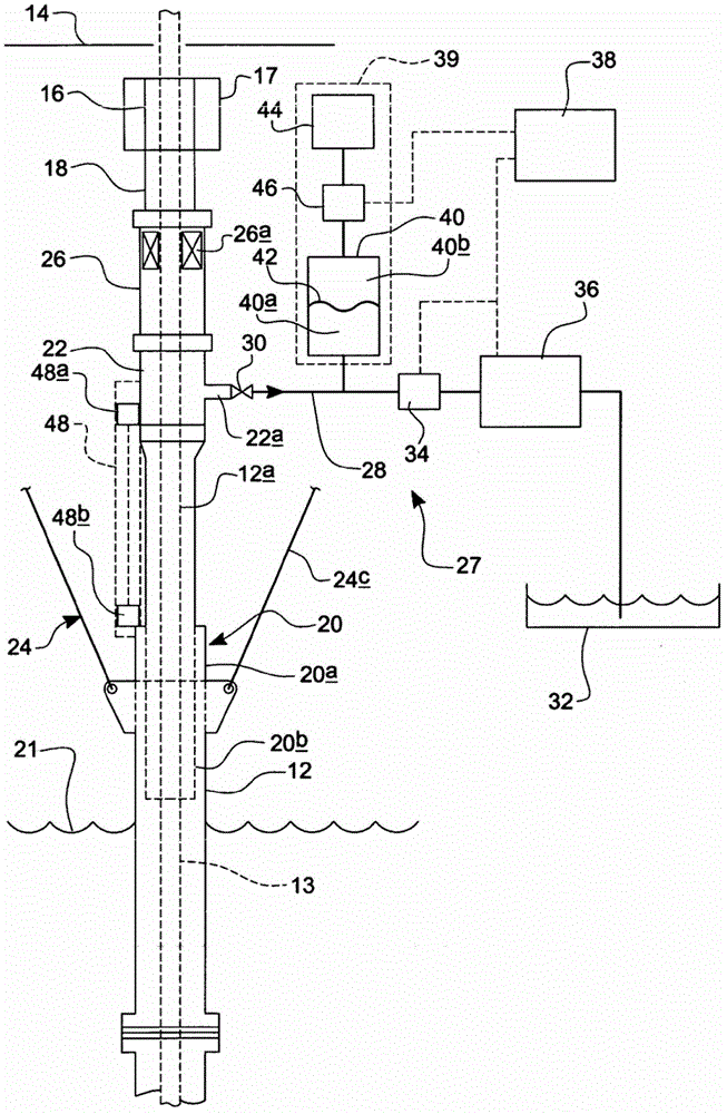
[0030] now refer to figure 1 , shows a riser system 10 comprising a riser 12, the lower end of which connects to a wellhead (not shown), in this example installed at the subsea surface at the wellhead by a blowout preventer (BOP) stack (not shown) or mud pipe. Such as figure 2 As shown, a drill string 13 extends from the wellbore, through the wellhead, the BOP stack, and down to the center of the riser 12 . The upper end of the riser 12 is connected to a drill floor 14 of the floating drilling rig, which is provided with equipment for driving the drill string, usually a rotary table or top drive (not shown). The riser assembly 10 is provided with a diverter 16 which provides an outlet for fluid from the riser 12 and is connected to the upper end of the riser 12 by a conventional ball or flexible joint 18. A ball or flexible joint 18 allows some angular movement of the riser 12 relative to vertical while still maintaining a substantially fluid seal between the riser 12 and ...


PUM


Abstract

A drilling system (10) including a drill string (13) which extends from a floating drilling rig to a well bore, and a tubular riser (12) which surrounds at least part of the portion of the drill string (13) between the well bore and drilling rig, the riser (12) having a telescopic joint (20) between a first tubular portion and a second tubular portion of the riser, the first tubular portion extending down to a well head at the top of the well bore and the second tubular portion extending up towards the drilling rig, the telescopic joint (20) comprising an inner tube part (20b) which is mounted within an outer tube part (20a), the drilling system (10) further including a riser closure device (26) which is mounted in the second tubular portion of the riser (12) and which is operable to provide a substantially fluid tight seal between the riser (12) and the drill string (13) whilst permitting the drill string (13) to rotate relative to the riser (12).

Description

technical field [0001] The present invention relates to a drilling system and a method of operating a drilling system, and in particular to a drilling system with a riser for off-shore drilling that allows pressurization of fluid in a riser. Background technique [0002] When drilling a subsea wellbore, a riser is provided to bring drilling fluid (mud), cuttings and other solids or liquids from the wellbore back to the surface. The drill string extends down the center of the riser, and the returning drilling fluid, cuttings, etc. flow along the annular space around the drill string in the riser (riser annulus). [0003] Where drilling of a wellbore is performed using a drill floor (such as a drill ship, semi-submersible rig, floating drilling or production platform), it is known to provide the wellbore with a sliding joint that allows the wellbore to follow the movement of the rig floor as the sea level changes. Elongated or shortened by the ups and downs of tides and waves...

Claims


Application Information

Patent Timeline
Patent Type & Authority Patents(China)
IPC IPC(8): E21B19/00E21B21/08E21B33/08
CPCE21B2021/006E21B33/085E21B19/006E21B21/08E21B21/085E21B17/01E21B17/085E21B19/004
Inventor C·莱藤伯格
Owner MANAGED PRESSURE OPERATIONS PTE
Why Eureka
Try Eureka