Apparatus For Dispensing A Pressurised Liquid

A technology of pressurized liquid and liquid, which is applied in the field of equipment for pressurizing and distributing multiple liquids, which can solve the problems of unusable devices and achieve the effect of improving distribution speed and simple structure

Inactive Publication Date: 2012-12-05
JENS KSA HLDG
View PDF10 Cites 0 Cited by
  • Summary
  • Abstract
  • Description
  • Claims
  • Application Information

AI Technical Summary

Problems solved by technology

Furthermore, other liquids with a certain sugar content, such as soft drinks and beer, will clog the interior of the device relatively quickly, rendering the device unusable due to the fact that especially sugar substances will adhere to the inner surface inside the reservoir

Method used


Image

  • Apparatus For Dispensing A Pressurised Liquid
  • Apparatus For Dispensing A Pressurised Liquid
  • Apparatus For Dispensing A Pressurised Liquid

Examples


Embodiment Construction

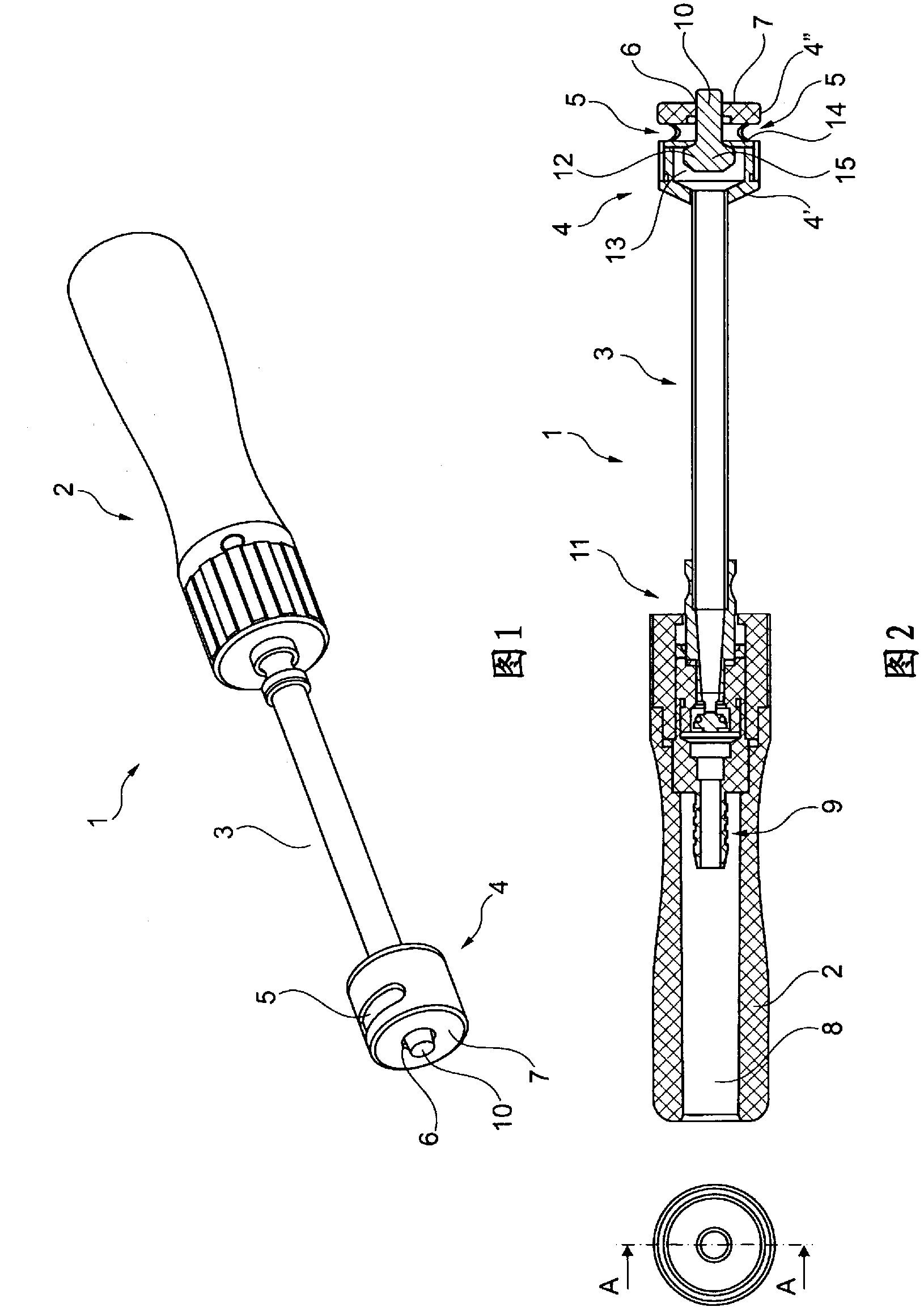
[0049] figure 1 A preferred embodiment of the invention is shown in . The device 1 comprises a handle 2 , a stem 3 and an outlet body 4 .

[0050] The handle is preferably made of plastic, injection molded, and of a size that is comfortable in use, but other than these requirements, the handle may be made of any material and in any shape or form as the user sees fit.

[0051] The stem 3 has such a length that the outlet body 4 can be brought into contact with the bottom of the can or glass without submerging the whole device in the can or the dispensed liquid. The connection between the handle and the rod is preferably detachable, as will be referred to figure 2 It is stated, but it is also conceivable that a non-separable rod could be used in conjunction with the handle.

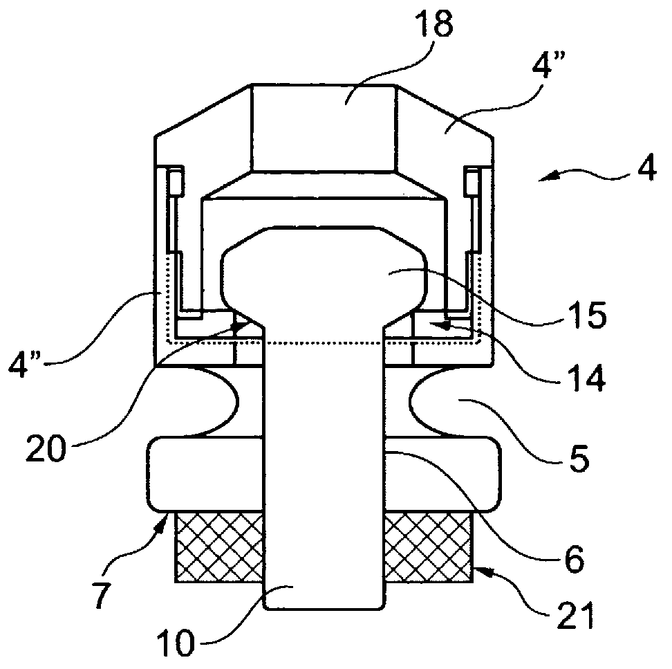
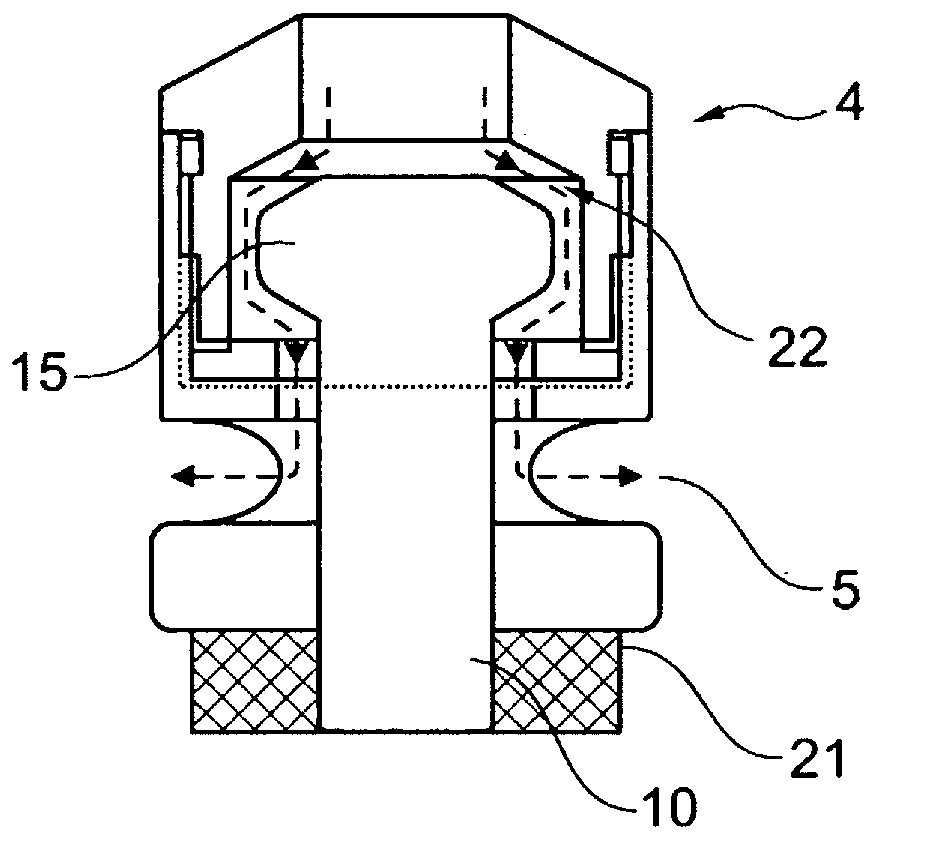
[0052] The outlet body 4 is provided with an outlet opening 5 and an opening 6 in the bottom surface 7 of the outlet body 4 . A stem 10 of a valve body (not shown) protrudes outwards through an opening...


PUM


Abstract

Device (1) for dispensing a liquid under pressure where said device comprises connection means (9) for connecting said device to the source of liquid, and where the device in the opposite end of the connection means has an outlet body (4) which outlet body may be brought into a closed position where no liquid is dispensed, and an open position where liquid is dispensed, which outlet body incorporates a separate valve body (12) cooperating with a valve seat (14), where said valve body has a head portion (15) and a stem portion (10), where said stem portion in the closed position extends out of an opening in said outlet body, and where a lower surface of said head portion in the closed position is in contact with said valve seat and in said open position is out of contact with said valve seat.

Description

technical field [0001] The invention relates to a device for dispensing pressurized liquids and a device for pressurized dispensing of portions of liquids incorporating at least one device according to the invention. Background technique [0002] Various devices have been devised in the art to dispense pressurized liquids, such as soft drinks or beer. One such example is disclosed in EP0077910, which discloses a dispensing nozzle. The nozzle includes an outer tubular member and an inner tubular member arranged coaxially inwardly of each other. The inner coaxial part is provided with an elastic sealing element at the distal end and the outer tubular part has been provided with a nozzle-shaped open end. By displacing the inner tubular member relative to the outer tubular member along the common passage, the resilient member will contact or disengage the output opening in the outer tubular member, thereby opening or closing liquid flow depending on the position of the inner t...

Claims


Application Information

Patent Timeline
Patent Type & Authority Applications(China)
IPC IPC(8): B67D1/00B67D1/14B67C3/26B67D1/12
CPCB67D1/1411B67D1/0082B67D1/1466B67D1/0084B67D1/124Y10T137/9029
Inventor J·K·S·安德森
Owner JENS KSA HLDG
Why Eureka
Try Eureka