Spiral sheer reinforcement and bar arrangement of slab steel bars using same

A technology of spiral steel bars and reinforcements, applied to structural elements, floor slabs, building components, etc., can solve the problems of complex production of shear reinforcements, achieve simple production and supply, reduce the number of steel bars, and reduce the effect of welding parts

Inactive Publication Date: 2015-04-08
OCTAGON ENG
View PDF4 Cites 0 Cited by
  • Summary
  • Abstract
  • Description
  • Claims
  • Application Information

AI Technical Summary

Problems solved by technology

Although this method is compared to Figure 1d The three-dimensional truss has the advantage of reducing the amount of reinforcement, but the production of shear reinforcements is still complicated, and there is still the problem of setting shear reinforcements in one direction

Method used


Image

  • Spiral sheer reinforcement and bar arrangement of slab steel bars using same
  • Spiral sheer reinforcement and bar arrangement of slab steel bars using same
  • Spiral sheer reinforcement and bar arrangement of slab steel bars using same

Examples


Embodiment Construction

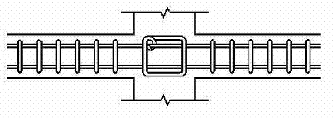
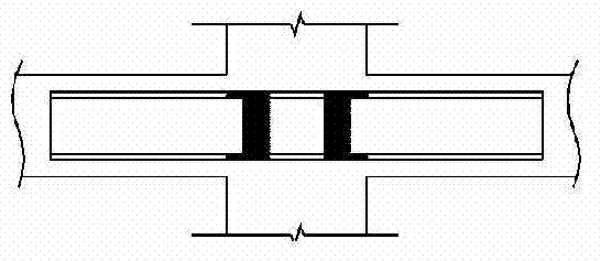
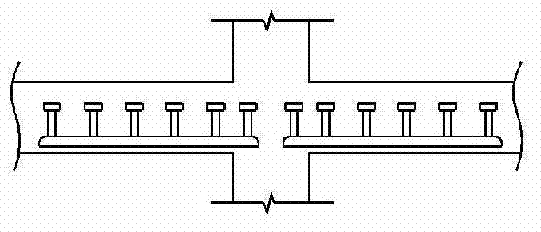
[0024] The spiral shear reinforcement according to the present invention is characterized in that it includes: a spiral steel bar, which is bent into a spiral shape along the length direction, and is formed by a rectangular elliptical spiral whose height is greater than the width and draws an arc toward the width direction; An upper steel bar, which is arranged inscribed along the length direction of the spiral steel bar at the upper high point of the spiral steel bar or on the side surface of the spiral steel bar to join; a lower steel bar, which is arranged inscribed along the length direction of the spiral steel bar. The lower low point of the helix or the lower part of the other side of the helix.

[0025] According to the plate reinforcement structure of the present invention, it is characterized in that it includes: the steel bars in the lower part of the plate, the main reinforcement and the force reinforcement are arranged in a grid pattern; the upper reinforcement of t...


PUM


Abstract

The present invention relates to a sheer reinforcement of a column-slab joint in a flat-plate structure, and more particularly, to a sheer reinforcement capable of maximizing sheer reinforcing effects using a minimal amount of steel bars, and to a preferable bar arrangement of slab steel bars using same. The spiral sheer reinforcement according to the present invention comprises: a spiral steel hoop bent in a spiral shape along a lengthwise direction thereof to form elongated arcuate ellipses widthwise such that the height is greater than the width thereof; a first arrangement of upper steel bars arranged lengthwise along the spiral steel hoop and joined to the uppermost points of the spiral steel hoop or top portions at one inner side of the spiral steel hoop; and a first arrangement of lower steel bars arranged lengthwise along the spiral steel hoop and joined to the lowermost points of the steel hoop or bottom portions at the other inner side of the spiral steel hoop. The bar arrangement of slab steel bars according to the present invention is characterized by arranging the spiral sheer reinforcement between upper and lower steel bars about a column.

Description

technical field [0001] The present invention relates to the shear reinforcement of the joint between a column and a slab in a beamless slab structure. More specifically, it relates to a shear reinforcement that can increase the shear reinforcement effect with the least amount of reinforcement and preferably utilizes the The reinforcement structure of the flat plate reinforcement of the shear reinforcement body is described. Background technique [0002] The beamless slab structure is a structure in which the floor is composed of only flat plates without beams, and the load of the flat plates is directly transmitted to the columns. In the beamless slab structure, due to the excessive stress concentration around the column, the possibility of the slab being sheared by the perforation is high. All enhanced. [0003] In the traditional shear reinforcement method, there is a method of enlarging the cross-section by constructing a drop panel and a capital around the column, but ...

Claims


Application Information

Patent Timeline
Patent Type & Authority Patents(China)
IPC IPC(8): E04B5/43E04C5/06
CPCE04C5/0618E04C5/0645E04B1/165E04B1/38E04B5/43
Inventor 柳承一
Owner OCTAGON ENG
Why Eureka
Try Eureka