
Power control circuit

A power control circuit, power supply voltage technology, applied in the direction of control/regulation system, electrical components, adjusting electrical variables, etc., can solve the problems of inconsistent logic sequence, unsatisfied DC voltage, slowness, etc.

Inactive Publication Date: 2012-12-12
INVENTEC CORP
View PDF5 Cites 4 Cited by
  • Summary
  • Abstract
  • Description
  • Claims
  • Application Information

AI Technical Summary

Problems solved by technology

[0003] However, during the voltage measurement process, the slope of the power-on working voltage of the chip is relatively small, and the voltage value of the working voltage end of the chip electrically connected to it rises relatively slowly. When the normal operating voltage is reached, it is possible that the chip enable voltage V EN The predetermined enable threshold has been met, so that the DC voltage output by the chip does not meet the expected voltage value
For example, suppose the power-on working voltage threshold of the chip is 5V, and the chip enable voltage threshold is 2V. When the voltage displayed on the chip’s working voltage terminal is 3.9V, if the voltage displayed on the chip V, then, the voltage timing at this time is that the chip enable signal arrives earlier than the normal power-on signal, which is obviously inconsistent with the normal logic timing, and this abnormal timing is likely to cause the actual output voltage to deviate from the expected voltage value

Method used


Image

  • Power control circuit
  • Power control circuit
  • Power control circuit

Examples


Embodiment Construction

[0027] The specific implementation manners of the present invention will be described in further detail below with reference to the accompanying drawings.

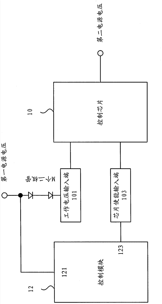
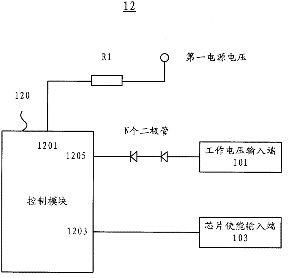
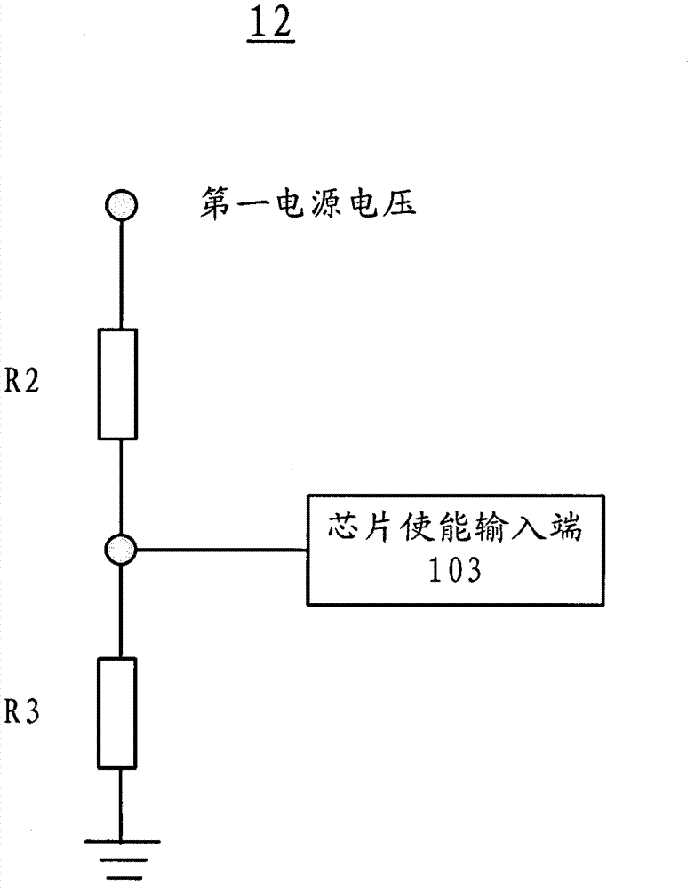
[0028] figure 1 A structural block diagram of a power control circuit according to one aspect of the present invention is shown. refer to figure 1 , the power supply control circuit of the present invention includes a control chip 10 and a control module 12 . Wherein, the control chip 10 includes a working voltage input terminal 101 and a chip enable input terminal 103. Specifically, the working voltage input terminal is electrically connected to the first power supply voltage via a series connection module composed of M diodes, wherein the series The anode of the first diode of the connected module is electrically connected to the first power supply voltage, and the cathode of the diode at the end of the series connected module is electrically connected to the working voltage input terminal 101, and M is a natural numbe...


PUM


Abstract

The invention provides a power control circuit. The power control circuit comprises a control chip, a chip enable input end and a control module, the control chip includes a working voltage input end, the working voltage input end is electrically connected to a first power voltage through a series connection module formed by M diodes, when the voltage of the chip enable input end is higher than an enable voltage threshold value, the control chip outputs a second power voltage, the control module is provided with a control input end and a control output end, the control input end and the control output end are electrically connected to the first power voltage and the chip enable input end respectively, and when the voltage value of the working voltage input end is lower than the working voltage threshold value of the control chip, the voltage value of the chip enable input end is lower than the enable voltage threshold value. By means of the power control circuit, the control input end is electrically connected to the first power voltage, the control output end is electrically connected to the chip enable input end, and when the voltage value of the working voltage input end of the control chip is lower than the working voltage threshold value, the voltage value of the enable input end of the control chip is lower than the enable voltage threshold value.

Description

technical field [0001] The invention relates to the output control technology of a DC power supply, in particular to a power supply control circuit in the DC power supply. Background technique [0002] In the prior art, a special power conversion chip is usually used for control in the circuit design of the DC power supply. Generally, the power conversion chip has a power-on working voltage V CC and chip enable voltage V EN , when the power-on operating voltage V CC When the rate of rise is large enough, the power conversion chip first reaches the normal power-on working voltage, and then the chip enable voltage V EN Satisfy the predetermined enabling threshold, so that the chip outputs the desired DC voltage, such as 5V. [0003] However, during the voltage measurement process, the slope of the power-on working voltage of the chip is relatively small, and the voltage value of the working voltage end of the chip electrically connected to it rises relatively slowly. When...

Claims


Application Information

Patent Timeline
IPC IPC(8): H02M3/155
Inventor 赵志强
Owner INVENTEC CORP
Learn More