

Novel rocker arm lathe structure
A lathe, a new type of technology, applied in the field of lathes, can solve the problems of reduced precision of lathes and reduced service life of lathes, and achieve the effect of overcoming the reduction of precision and reduced service life
Inactive Publication Date: 2012-12-19
唐德川
View PDF0 Cites 0 Cited by
- Summary
- Abstract
- Description
- Claims
- Application Information
AI Technical Summary
Problems solved by technology
[0003] The purpose of the present invention is to provide a new structure of the rocker lathe, to overcome the existing rocker lathe which is easy to cause the precision of the lathe to be reduced, and at the same time, also reduce the defect of the service life of the lathe
Method used
View moreImage
Smart ImageViewing Examples

Examples
Embodiment Construction
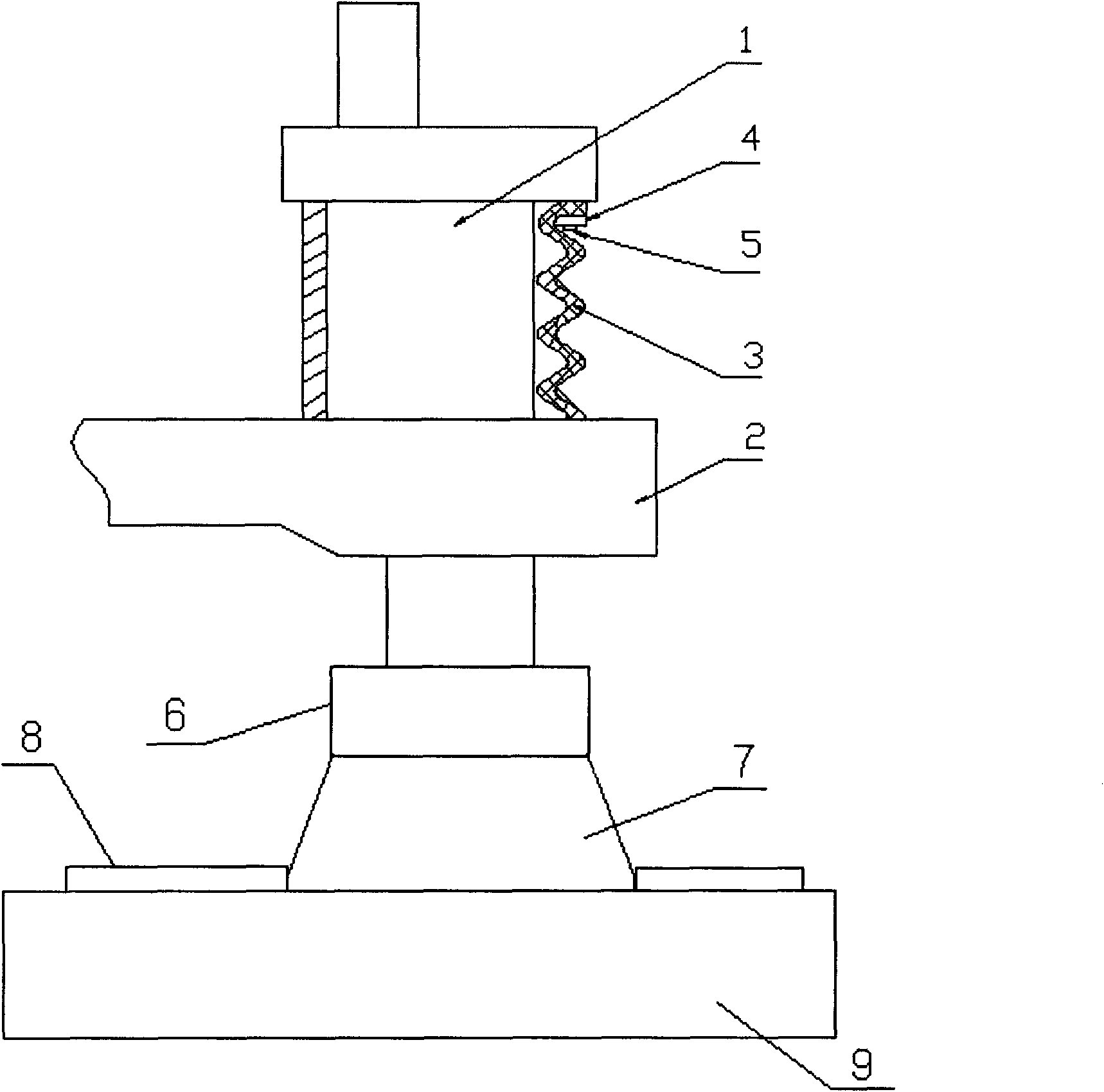
[0008] The structure of the rocker lathe has a rocker arm 2, on the two-way column 1 at both ends of the rocker arm 2, a multi-position spring 3 is respectively installed, and one end of the multi-position spring 3 is fixed on the column 1 by using a flange 4 and a fastening bolt 5 , because the multi-position bomb 3 has a certain degree of elasticity, the contact part of the rocker arm 2 is tightly pressed against the rocker arm, the small column seat 6 and the large column seat 7 are fixed together by threads, and the large column seat 7 is installed on the workbench 8 Above, the workbench 8 is fixedly installed on the base 9.
Login to View More PUM
 Abstract
The invention discloses a novel rocker arm lathe structure. Two-way upright posts at two ends of a rocker arm are respectively sleeved with a multi-position spring; one ends of the multi-position springs are fixed on the upright posts by using flanges and fastening bolts; the multi-position springs have a certain elasticity, so that a contact part of the multi-position springs and the rocker arm are tightly pressed on the rocker arm; a large upright post seat and a small upright post seat are fixed together through a screw thread; the large upright post seat is arranged on a workbench; and the workbench is fixedly arranged on a base.
Description
technical field [0001] The invention relates to a structure of a rocker lathe, in particular to a novel structure of a rocker lathe, and belongs to the technical field of lathes. Background technique [0002] The rocker lathe is a kind of lathe that is used in a large amount in the machining factory. In the actual use process, it is often found that the column of the rocker lathe and the matching part of the rocker and the column are worn, which may easily reduce the precision of the lathe. , At the same time, it also reduces the service life of the lathe. Contents of the invention [0003] The object of the present invention is to provide a new structure of a rocker lathe, which overcomes the defects that the existing rocker lathes tend to reduce the precision of the lathe, and at the same time, reduce the service life of the lathe. [0004] The technical solution adopted by the present invention to achieve the above object is: a new type of rocker arm lathe structure, w...
Claims
Login to View More Application Information
Patent Timeline
 Patent Type & Authority Applications(China)
IPC IPC(8): B23B3/06B23B25/00
Inventor 唐德川
Owner 唐德川