Mixing system of injected pulp in metro shield construction

A technology in subway shield tunneling and construction, applied in underground chambers, cement mixing devices, chemical instruments and methods, etc., can solve the problems of increased labor costs, time-consuming and laborious, inconvenient cleaning, etc., and achieve labor cost savings and convenient use , the effect of convenient washing

Inactive Publication Date: 2019-04-05
陈明
View PDF0 Cites 0 Cited by
  • Summary
  • Abstract
  • Description
  • Claims
  • Application Information

AI Technical Summary

Problems solved by technology

After mixing the pressure-injected grout, it is necessary to clean the mixing equipment such as the horizontal mixer for the next use. The prior art is extremely inconvenient for cleaning the horizontal mixer, which is time-consuming and labor-intensive, and increases labor costs.

Method used


Image

  • Mixing system of injected pulp in metro shield construction
  • Mixing system of injected pulp in metro shield construction
  • Mixing system of injected pulp in metro shield construction

Examples


Embodiment

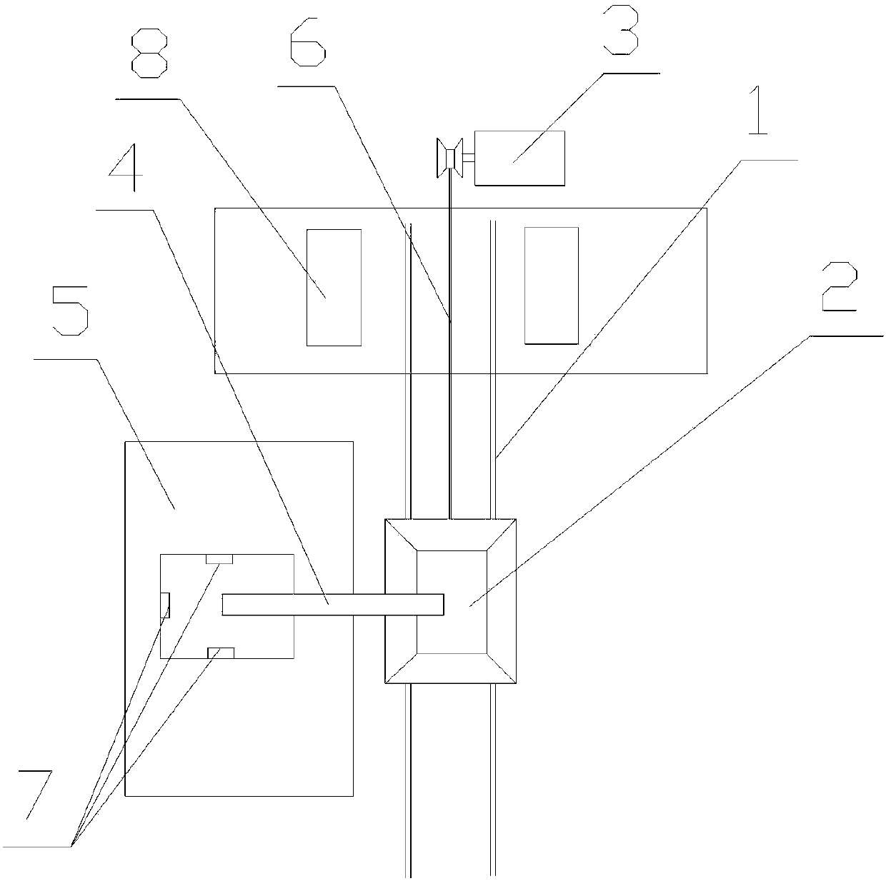
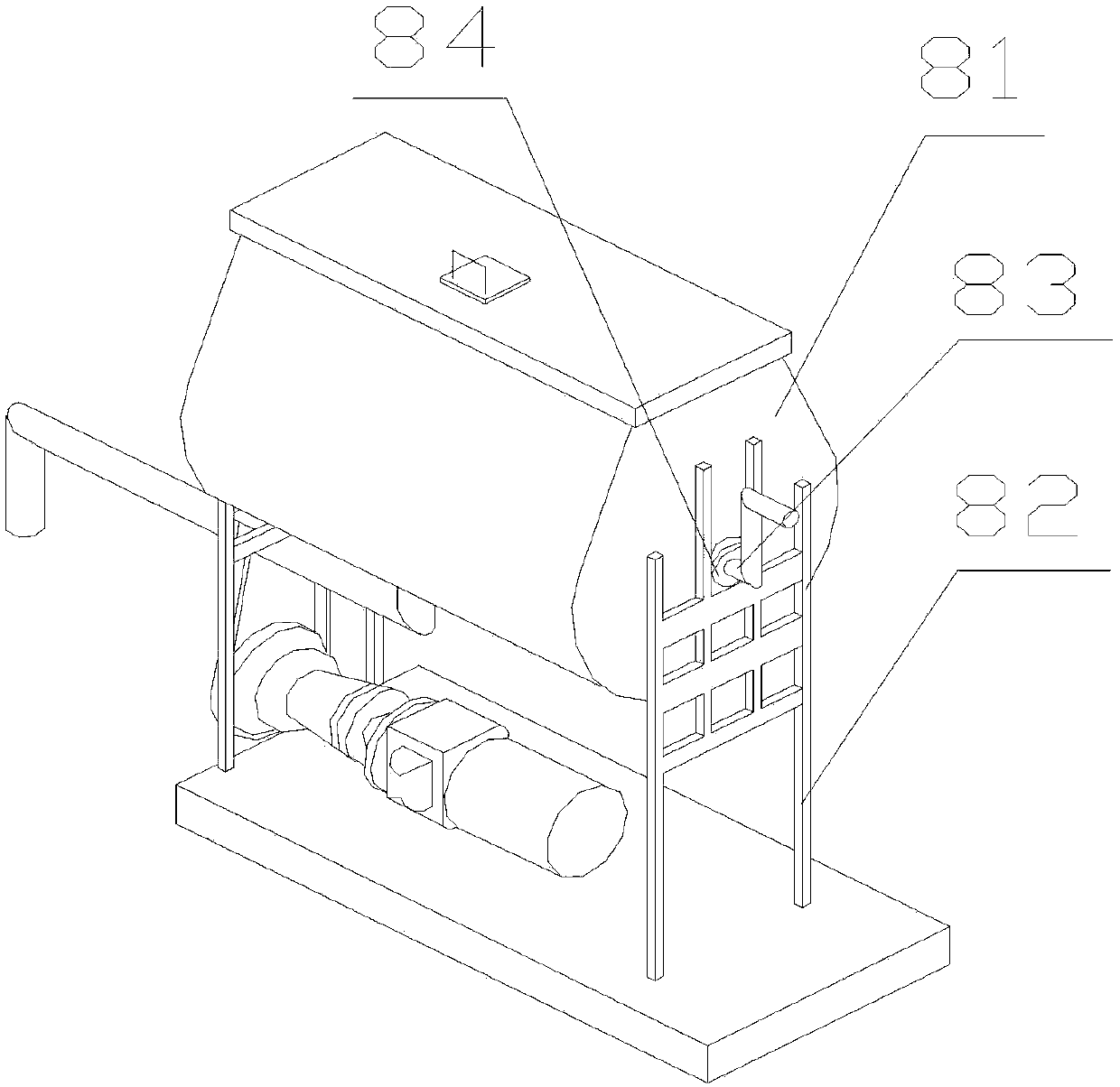
[0016] Such as Figure 1-3 As shown, a mixing system for medium-pressure grouting in subway shield construction includes a track 1, a bucket car 2, a hoist 3, a screw conveyor 4, a sand field 5, and a horizontal mixer 8, and the track 1 is vertically arranged , the bucket truck 2 is located on the track 1, the hoist 3 is installed on the top of the track 1 and is connected with the bucket truck 2 through a traction wire rope 6, and is used for pulling the bucket truck 2 to move. The screw conveyor 4 and the sand field 5 They are all located on the same side of the track 1. The sand field 5 is provided with more than one sand and gravel outlet 7, and the two ends of the screw conveyor 4 are respectively provided with a material inlet port and a material outlet port. The stone discharge port 7 is connected, and the discharge port extends to the track 1 and is located above the bucket car 2; the horizontal mixer 8 mainly includes a material cylinder 81 and a frame 82, and the two...


PUM


Abstract

The invention discloses a mixing system of injected pulp in metro shield construction. The mixing system comprises a rail, a trolley, a windlass, a spiral conveyor, a sand field and a horizontal stirrer; the rail is longitudinally arranged; the trolley is positioned on the rail; the windlass is mounted at the top end of the rail, and is connected with the trolley through a traction steel wire rope; the spiral conveyor and the sand field are both positioned on the same side of the rail; the horizontal stirrer comprises a barrel and a frame; the barrel is mounted on the frame through a connecting shaft; a racket is connected to the connecting shaft; the frame is provided with a pallet matched with the ratchet; an adjusting mechanism is arranged between the ratchet and the frame, and comprises a chute and a slide block; a limiting rod is arranged in the chute; the slide block is rotationally connected with the pallet; and a torsion spring is arranged in the connected place. The mixing system solves the problem of inconvenience to clean of mixing equipment in the prior art.

Description

technical field [0001] The invention relates to a mixing system for pressure grouting in subway shield construction. Background technique [0002] Shield method is a comprehensive construction technology. The main content of the shield tunneling method construction is: first build a shaft or foundation pit at one end of a certain section of the tunnel for the shield to be installed in place. The shield starts from the reserved hole in the wall of the vertical shaft or foundation pit, and advances to the designed reserved hole of another vertical shaft or foundation pit along the design axis in the stratum. The stratum resistance encountered during shield tunneling is transmitted to the assembled prefabricated lining at the tail of the shield through the shield jack. The shield is a circular steel cylinder structure that can support the formation pressure and can be pushed in the formation. Its diameter is slightly larger than the diameter of the tunnel lining. Various type...

Claims


Application Information

Patent Timeline
Patent Type & Authority Applications(China)
IPC IPC(8): B28C5/00B28C7/06B28C7/10E21D11/10
CPCB28C5/00B28C7/068B28C7/10E21D11/10E21D11/105
Inventor 陈明
Owner 陈明
Why Eureka
Try Eureka