

Novel driller rocker arm structure
A drilling machine and a new type of technology, applied in the field of machine tools, can solve the problems of reducing the service life of the machine tool and easy to wear, and achieve the effect of overcoming the phenomenon of breaking.
Inactive Publication Date: 2013-06-05
侯勤成
View PDF0 Cites 0 Cited by
- Summary
- Abstract
- Description
- Claims
- Application Information
AI Technical Summary
Problems solved by technology
[0005] Beneficial effects: the present invention reduces the eccentric moment generated by the rocker arm to a minimum level by installing the nut on the rocker arm, and effectively overcomes the breakage phenomenon existing in the existing rocker arm, resulting in the cooperative sliding of the rocker arm and the column Easy to wear between surfaces, reducing the service life of the machine tool
Method used
View moreImage
Smart ImageViewing Examples

Examples
Embodiment Construction
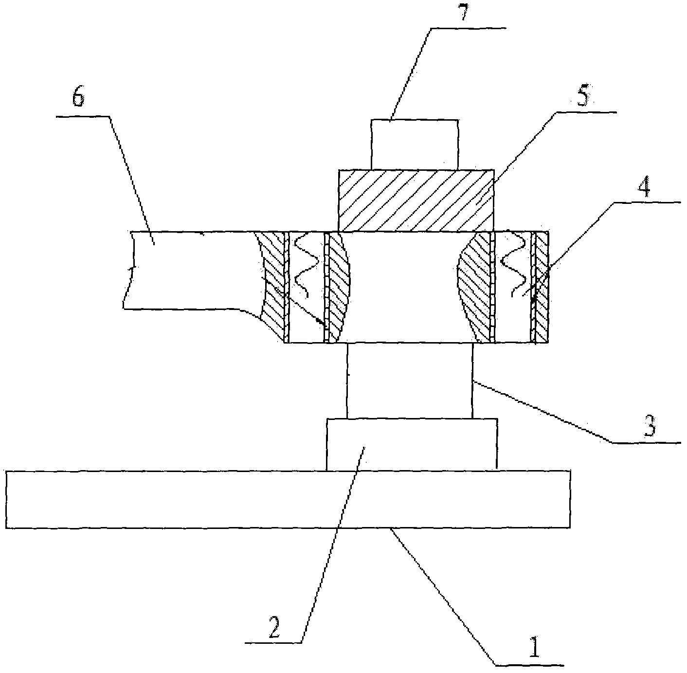
[0008] The rocker arm structure of the drilling machine has a base (1), and a column base (2) is connected to the base (1). A column (3) is installed on the column base (2), and the nut (4) is installed on the rocker arm (6). Above, the rotary motor (7) is installed on the reduction box (5), one end is docked with the nut (4), and the other end is docked with the rocking arm (6).
Login to View More PUM
 Abstract
Disclosed is a novel driller rocker arm structure. A stand column pedestal is connected on a pedestal, and a stand column is installed on the stand column pedestal. A nut is installed on a rocker arm. A rotating motor is installed on a reduction gearbox, one end of the rotating motor and the nut are in butt joint, and the other end of the rotating motor and the rocker arm are in butt joint. According to the novel driller rocker arm structure, the nut is installed on the rocker arm, eccentric torque generated by the rocker arm is reduced to the minimum degree, and therefore the defects that the breaking phenomenon can occur in an existing rocker arm, so that abrasion can happen easily between the matching sliding surface of the rocker arm and the matching sliding surface of the stand column, and the service life of a machine tool is shortened are effectively overcome.
Description
technical field [0001] The invention relates to a rocker arm structure, in particular to a novel drilling machine rocker arm structure, which belongs to the technical field of machine tools. Background technique [0002] At present, the rocker joint mechanism of the radial drilling machine is composed of a motor, a reduction box, and a screw. After the rotation of the motor is decelerated by the gear box, the screw is driven to rotate. Since the screw is connected to the rocker arm of the drilling machine, It drives the movement of the rocker arm; since the rocker arm is a cantilever beam structure, the rocker arm will generate a certain eccentric moment, and this eccentric moment is also loaded on the top of the screw, so the screw is not only easy to wear, but may even The danger of breaking, similarly, due to the existence of eccentric moment, it will also cause easy wear and tear between the matching sliding surfaces of the rocker arm and the column, reducing the service...
Claims
Login to View More Application Information
Patent Timeline
 Patent Type & AuthorityApplications(China)
IPC IPC(8): B23B39/12
Inventor侯勤成
Owner侯勤成