Power head lifting mechanism of gantry movable type numerical-control drilling and milling machine

A lifting mechanism and power head technology, which is applied to metal processing machinery parts, metal processing equipment, feeding devices, etc., can solve the problems of shortened tool life, poor cutting precision, large hanging body of the lifting spindle, etc., to reduce the eccentric moment , Reduce the occupied space, improve the service life and the effect of machine tool machining accuracy

Inactive Publication Date: 2013-07-17
WUXI HUALIAN PRECISION MACHINERY
View PDF6 Cites 0 Cited by
  • Summary
  • Abstract
  • Description
  • Claims
  • Application Information

AI Technical Summary

Problems solved by technology

In the traditional large-scale gantry mobile CNC drilling and milling machine, the linear guide rail and ball screw used in the transmission structure of the lifting drilling and milling power head are installed on the back of the lifting spindle and placed in parallel with the lifting spindle, so the whole The transmission structure will be arranged very wide, thereby increasing the width of the machine tool. At the same time, due to the large hanging body of the lifting spindle in this arrangement, eccentric moments will be generated during cutting, which will easily shorten the service life of the tool and cause poor cutting accuracy.

Method used


Image

  • Power head lifting mechanism of gantry movable type numerical-control drilling and milling machine
  • Power head lifting mechanism of gantry movable type numerical-control drilling and milling machine
  • Power head lifting mechanism of gantry movable type numerical-control drilling and milling machine

Examples


Embodiment Construction

[0018] The specific implementation manner of the present invention will be described below in conjunction with the accompanying drawings.

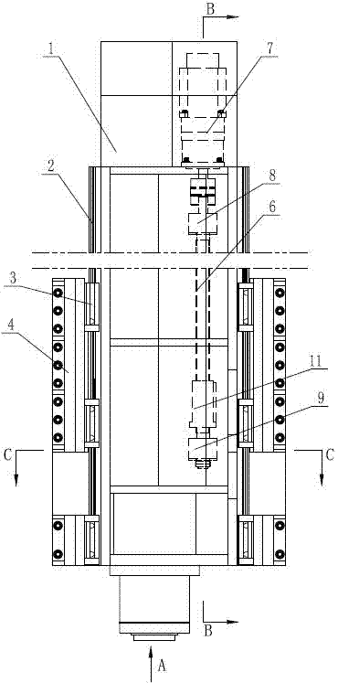
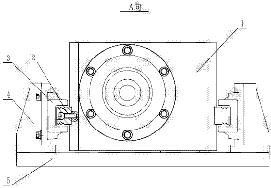
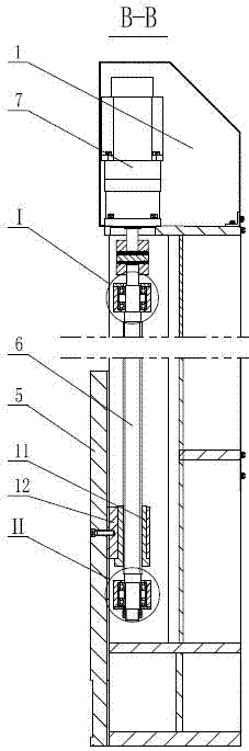
[0019] See figure 1 , figure 2 , image 3 , the present invention includes a power head box body 1, a ball screw pair and a linear guide rail pair, the linear guide rails 2 in the linear guide rail pair are fixedly installed on both sides of the power head box body 1, and the linear guide rails 2 are slidably connected with guide slides block 3, the guide slider 3 is fixedly installed on the installation base 4, the installation base 4 is fixedly installed on the moving plate 5, the linear guide rail 2 and the guide slider 3 constitute the linear guide rail pair; the ball screw pair is mounted on the power In the head box 1, the ball screw 6 in the ball screw pair is connected to the output shaft of the servo motor 7, the axis of the ball screw 6 is parallel to the linear guide rail 2, and the servo motor 7 is fixed in the power head bo...


PUM


Abstract

A power head lifting mechanism of a gantry movable type numerical-control drilling and milling machine comprises a power head box. The power head lifting mechanism is characterized in that linear guide rails are fixedly mounted on two sides of the power head box, guide sliders are slidably connected onto the linear guide rails and are fixedly mounted on mounting seats, and the mounting seats are fixedly mounted on a moving plate; and a ball screw is fixedly arranged in the power head box and is in transmission connection with an output shaft of a servo motor, the axis of the ball screw is parallel to the linear guide rails, the servo motor is fixedly arranged inside the power head box, an upper bearing block and a lower bearing block are rotationally mounted on the ball screw, bearings are arranged in both the upper bearing block and the lower bearing block, the upper bearing block and the lower bearing block are fixedly connected with the power head box, a nut is screwed on the ball screw and is positioned between the upper bearing block and the lower bearing block and is fixedly connected onto a nut seat, and the nut seat is fixedly connected onto the moving plate. The power head lifting mechanism has the advantages that eccentric torque generated by a cutting tool is effectively reduced, the service life of the tool is prolonged, the cutting machining precision of the tool is improved, and space occupied by the power head lifting mechanism is reduced.

Description

technical field [0001] The invention relates to the technical field of numerical control drilling and milling equipment, in particular to a drag chain installation structure in a gantry mobile numerical control drilling and milling machine. Background technique [0002] The CNC gantry drilling and milling machine is a processing equipment for large parts. The structure of the gantry mobile CNC drilling and milling machine is characterized by the movement of the gantry frame and the fixed worktable, so there is no limit to the weight of the workpiece, and super long parts can be processed. With its automation With the continuous improvement of performance and compounding degree, it has been widely used. In the traditional large-scale gantry mobile CNC drilling and milling machine, the linear guide rail and ball screw used in the transmission structure of the lifting drilling and milling power head are installed on the back of the lifting spindle and placed in parallel with th...

Claims


Application Information

Patent Timeline
Patent Type & Authority Applications(China)
IPC IPC(8): B23Q5/28
Inventor 陆松茂武文周敏铨薛静清邵燕瑛
Owner WUXI HUALIAN PRECISION MACHINERY
Why Eureka
Try Eureka